Ustang, Eries, Sizing – Watts M1115 User Manual
Page 3: Cavitation chart
12541 Gulf Freeway
•
Houston, Texas 77034
•
(Ph) 713.943.0688
•
(Fx) 713.944.9445
•
www.watts.com
M
ustang
s
eries
Sizing
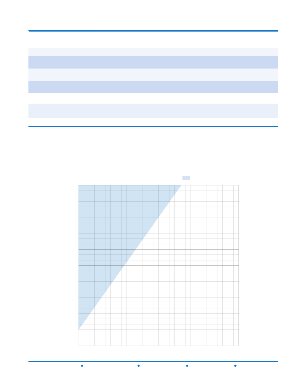
CAVITATION ZONE
INLET PRESSURE - PSI
OUTLET PRESSURE - PSI
300
280
260
240
220
200
180
160
140
120
100
80
60
40
20
0
10 20
40
50
60
70
80
90
130 140
120
110
100
30
CAVITATION CHART
After selecting the valve size, locate inlet and outlet pressures on this chart. If the intersection point falls
in the shaded area, cavitation can occur. Operation of valves continually in the cavitation zone should be
avoided. Consult Watts ACV for alternatives.
Cavitation Chart
NOTE: The above chart is a suggested guide. Inlet pressure, outlet pressure, minumum, normal and maximum flow rates should
be considered for specific valve sizing. Contact Watts ACV for details.
Size (in)
1-1/4
1-1/2
2
2-1/2
3
4
6
8
10
12
14
16
Maximum Continuous
(GPM)
95
130
210
300
485
800
1850
3100
5000
7000
8400
11100
Maximum Intermittent
(GPM)
119
161
265
390
590
1000
2300
4000
6250
8725
10500 13300
Minimum Continuous
(GPM)
1
1
1
20
30
50
115
200
300
400
500
650
Valve Size (in)
1-1/4
1-1/2
2
2-1/2
3
4
6
8
10
12
14
16
fl.oz.
4
4
4
10
10
22
70
-
-
-
-
-
U.S. Gal
-
-
-
-
-
-
-
1-1/4
2-1/2
4
6-1/2
9-1/2
Valve Size (in)
1-1/4
1-1/2
2
2-1/2
3
4
6
8
10
12
14
16
Travel (in)
3/8
3/8
1/2
5/8
3/4
1
1-1/2
2
2-1/2
3
3-1/2
4
M115 (Globe)
M1115 (Angle)