Pressure –– temperature –– flow rate, Capacity, Figure 4 – temperature adjustment – Watts LFMMV User Manual
Page 3: Notice
Pressure –– Temperature –– Flow Rate
Minimum Supply Pressure Static: 30psi (207 kPa)
Inlet Temperatures: hot inlet, 120°F – 180°F (49°C – 82°C),
cold inlet, 39°F – 85°F (4°C – 29°C)
Hot Water Inlet to Outlet Differential Temperature: 5°F (3°C)
Temperature Out: Field range: 80°F – 120°F (27°C – 49°C),
adjustable; Accurate within ±3°F (1.7°C)
†
Maximum Temperature: 200°F (93°C)
Maximum Pressure: 150psi (1034 kPa)
Minimum Flow: 0.5 gpm (1.9 lpm) @.08psi (0.55 kPa)
†
Maximum Flow: 20 gpm (76 lpm) @ 125psi (862 kPa)
†
Maximum Pressure Differential between
Hot & Cold Water Supplies: 25% maximum differential
Listing: ASSE 1017, ASSE 1069, ASSE 1070 and IAPMO cUPC
†
When tested in accordance with ASSE 1017, ASSE 1069, ASSE 1070
and IAPMO cUPC.
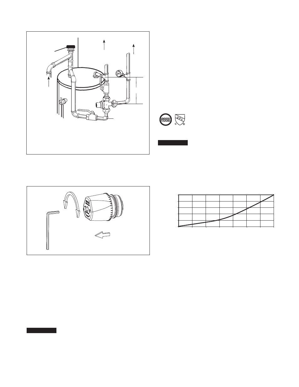
NOTICE
To prolong the life of the series LFMMV when used in an
ASSE 1017 application, it is recommended that it be trapped as
shown; i.e. the hot water inlet to the LFMMV should be 8"-12"
(200-305mm) below the hot water supply feed.
Flow curves are for reference. Actual flows may vary depending
on system temperatures and/or pressures.
*Flow curve with integral inlet filters and check valves
Capacity*
kpa psi
345 50
276 40
207 30
138 20
69 10
0
0
2
4
6
8
10
12
14
gpm
7.6
15
23
30
38
46
53
lpm
Pressure Drop
† Devices tested to ASSE 1069 or ASSE 1070 such as Watts
Series LFUSG or LFMMV should be used at fixture to
prevent possible injury.
Watts
Vacuum Relief
Valve
Watts Temperature
Gauge
Cold
Cold
Cold
LFMMV-M1
Tempered
†
Hot
Hot to
Appliances
Watts T&P
Relief Valve
*8" – 12"
H
C
M
Figure 3 – Typical ASSE 1017 Application
Hotter
3
/
32
" Hex Wrench
Turn
Colder
Unscrew, lift
cap to adjust
Figure 4 – Temperature Adjustment
1. Let the water flow for at least two minutes to allow supply
temperature to stabilize.
2. Calibrate the mixed water outlet temperature by placing a
thermometer in the mixed water stream.
3. To adjust the setting of the valve, loosen locking cap screw
with hex wrench, see Figure 4. Cap must be lifted
1
/
4
" to
adjust temperature. To increase the temperature, turn coun-
terclockwise. To decrease temperature turn clockwise.
4. Lower handle and tighten screw.
5. Check outlet temperature.
NOTICE
It is recommended that shutoff valve(s) be installed on the inlet(s)
to facilitate service of the LFMMV-M1 valve.