Watts LFMMV User Manual
Series lfmmv, Thermostatic tempering valves, Triple listed
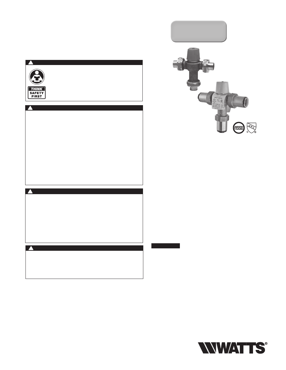
Series LFMMV
Thermostatic Tempering Valves
Sizes:
1
⁄
2
",
3
⁄
4
", 1"
IS-MMV-M1
LFMMV-UT-M1
LFMMV-QC-M1
Triple Listed!
ASSE 1017,
ASSE 1069 & ASSE 1070
WARNING
!
Read this Manual BEFORE using this equipment.
Failure to read and follow all safety and use infor-
mation can result in death, serious personal injury,
property damage, or damage to the equipment.
Keep this Manual for future reference.
You are required to consult the local building and plumbing
codes prior to installation. If the information in this manual is
not consistent with local building or plumbing codes, the local
codes should be followed. Inquire with governing authorities for
additional local requirements.
WARNING
!
FAILURE TO COMPLY WITH PROPER INSTALLATION
AND MAINTENANCE INSTRUCTIONS COULD
CONTRIBUTE TO THE VALVE FAILURE, RESULTING IN
INJURY AND/OR DEATH.
TO ENSURE THE ACCURATE AND RELIABLE
OPERATION OF THIS PRODUCT, IT IS ESSENTIAL TO:
• Properly design the system to minimize pressure and tem-
perature variations.
• This valve is not factory preset and can be adjusted to
deliver scalding temperatures. Check outlet temperature
to ensure it does not exceed 105°F (41°C). Make sure
temperature limit stop is properly re-set to maximum 105°F
(41°C) following valve maintenance or repair. Tampering
with limit stop in any way may result in scalding temperature
causing serious bodily harm and/or death.
WARNING
!
WARNING
!
Need for Periodic Inspection and Yearly Maintenance:
Periodic inspection and yearly maintenance by a licensed
contractor is required. Corrosive water conditions
and/or unauthorized adjustments or repair could render
the valve ineffective for service intended. Regular check-
ing and cleaning of the valve’s internal components
and check stops helps assure maximum life and proper
product function. Frequency of cleaning and inspection
depends upon local water conditions.
*The wetted surface of this product contacted by consumable water
contains less than 0.25% of lead by weight.
Installation Instructions
Valve should be installed and adjusted by a licensed contractor
in accordance with local codes and ordinances. Further, this
valve should be installed in a location where it is accessible for
cleaning, service or adjustment.
1.
Close both the hot and cold water shutoff valves upstream
nearest to the intended installation.
2. Bleed the remaining water from the system.
3. Connect the water supply to valve as shown in Figure 1, 2 or
3 depending on application. Supply piping must be flushed
clean before making connections to the valve.
4. Valve can be installed in any position. The inlet hot supply is to
be connected to the “H” side of the valve, the cold supply side
to the “C” side and the mixed water outlet to the “M” side.
5. Make sure union nuts are placed over tailpieces prior to solder-
ing or threading to pipe.
6. For valves with Quick-Connect tailpieces refer to "Quick-
Connect Installation" instructions below
NOTICE
To prevent damage to valve from excessive heat during
soldering, remove unions and gaskets from valve body prior
to soldering.
7. After soldering, flush piping and install valve using filter wash-
er on hot and cold water inlet and fiber washer on the mixed
water outlet.
8. Start-up: Open cold water supply, then hot water supply.
Inspect for leaks.
9. Adjust temperature to desired setting (see Temperature
Adjustment Section). Watts recommends a maximum
temperature of 105°F (41°C) for shower and bathing fixtures.