Model 4650, Water conditioner flow diagrams (cont’d.) 4 – Watts Fleck 4650 Hot Water Brass Valve User Manual
Page 11
Printed in U.S.A.
Page 11
MODEL 4650
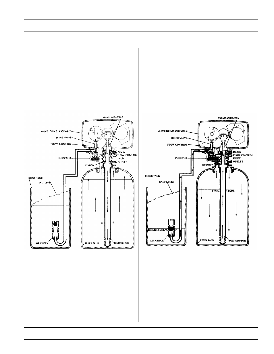
Water Conditioner Flow Diagrams (Cont’d.)
4
BRINE POSITION
3
BACKWASH POSITION
10 Minutes
First Portion of 50 Minute Fixed Cycle
Hard water enters the unit at the valve inlet - flows
around the lower piston groove and lower piston
land -down thru the center tube and out the
distributor - up thru the resin - thru the top of tank
passage - around the upper piston groove and out
the drain line.
Hard water enters the unit at the valve inlet - flows
around the lower piston groove - thru the injector
nozzle and orifice to draw brine from the brine tank.
The brine flows down thru the resin - into the distributor
- up thru the center tube - thru the center hole in the
piston and out the drain line.
See also other documents in the category Watts Accessories for water:
- PWMBVIH (4 pages)
- PWHSMULTI (2 pages)
- M100 / M1100 (2 pages)
- M113-41 (2 pages)
- M113-41 (1 page)
- 210-5 (2 pages)
- LF210-5 (2 pages)
- 88-CSI (2 pages)
- 1023B (2 pages)
- FD-200-RS (1 page)
- PWRO440 (8 pages)
- PWRO440 (2 pages)
- FD-200-VS (1 page)
- M6115-74 (7 pages)
- R44-16-1111000 (2 pages)
- R44-16-1111000 (40 pages)
- EMVII-6400-SS (2 pages)
- EMVII-6400-SS (4 pages)
- DBF-03 (2 pages)
- F110-10 (2 pages)
- F110-14 (6 pages)
- F113-6RFP (16 pages)
- 007DCDA (54 pages)
- LF709 (4 pages)
- 709DCDA (4 pages)
- LFWP19B (2 pages)
- WP12P-0812PB (2 pages)
- A-158A (1 page)
- A-158A (2 pages)
- RD-900 (1 page)
- M127-32 (1 page)
- M127-32 (2 pages)
- LF919 (3 pages)
- 919 (8 pages)
- M115-11 (2 pages)
- M115-11 (1 page)
- FS-720 (1 page)
- F116-5 (2 pages)
- F116-5 (1 page)
- 656 (1 page)
- LFN170 (2 pages)
- LFN170 (1 page)
- LFN170 (12 pages)
- LFN170 (2 pages)
- 288 1003 (1 page)