Model 4650, Water conditioner flow diagrams 1 – Watts Fleck 4650 Hot Water Brass Valve User Manual
Page 10
Printed in U.S.A.
Page 10
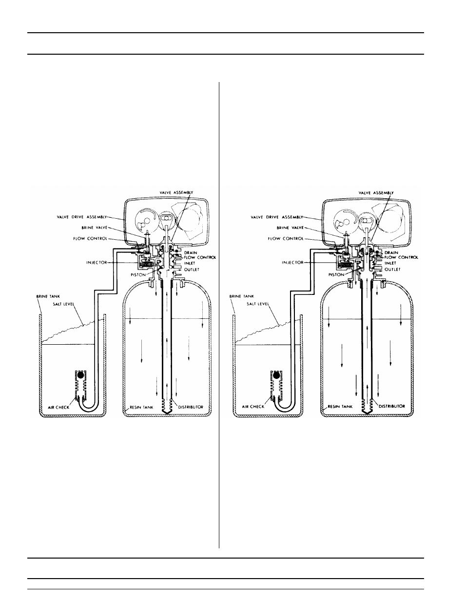
MODEL 4650
Water Conditioner Flow Diagrams
1
SERVICE POSITION
2
PRELIMINARY RINSE POSITION
Hard water enters the unit at the valve inlet - flows
around the lower piston groove - thru the passage to
the top of tank - down thru the resin and enters the
distributor as conditioned water. The conditioned
water flows up thru the center tube to the valve
outlet.
Hard water enters the unit at the valve inlet - flows
around the lower piston groove - down thru the top of
tank passage - downward thru the resin - up the
distributor tube - thru the center hole in the piston - over
the top edge of the piston and out the drain line.
5 Minutes
See also other documents in the category Watts Accessories for water:
- PWMBVIH (4 pages)
- PWHSMULTI (2 pages)
- M113-41 (2 pages)
- M113-41 (1 page)
- M100 / M1100 (2 pages)
- 210-5 (2 pages)
- LF210-5 (2 pages)
- 88-CSI (2 pages)
- 1023B (2 pages)
- FD-200-RS (1 page)
- PWRO440 (8 pages)
- PWRO440 (2 pages)
- FD-200-VS (1 page)
- M6115-74 (7 pages)
- R44-16-1111000 (2 pages)
- R44-16-1111000 (40 pages)
- EMVII-6400-SS (2 pages)
- EMVII-6400-SS (4 pages)
- DBF-03 (2 pages)
- F110-14 (6 pages)
- F110-10 (2 pages)
- F113-6RFP (16 pages)
- 709DCDA (4 pages)
- 007DCDA (54 pages)
- LF709 (4 pages)
- LFWP19B (2 pages)
- WP12P-0812PB (2 pages)
- A-158A (2 pages)
- A-158A (1 page)
- RD-900 (1 page)
- M127-32 (1 page)
- M127-32 (2 pages)
- 919 (8 pages)
- LF919 (3 pages)
- M115-11 (1 page)
- M115-11 (2 pages)
- FS-720 (1 page)
- F116-5 (2 pages)
- F116-5 (1 page)
- 656 (1 page)
- LFN170 (2 pages)
- LFN170 (2 pages)
- LFN170 (1 page)
- LFN170 (12 pages)
- 288 1003 (1 page)