Bryant Single Package Rooftop Electric Cooling/Gas Heating Units 580G User Manual
Page 33
TROUBLESHOOTING
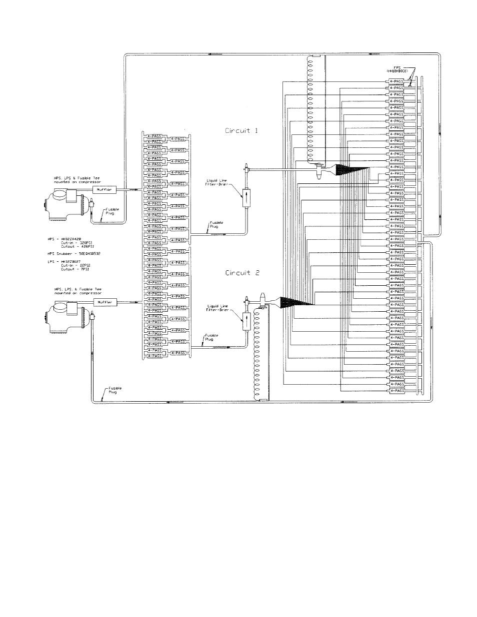
Typical refrigerant circuiting diagram is shown in Fig. 44.
I. DIAGNOSTIC LEDs (Light-Emitting Diodes)
There are 3 LEDs (red, yellow, and green) on the lower right
hand side of the control board. The red light is used to check
unit operation and alarms. A constant pulse is normal unit
operation. A series of quick blinks indicates an alarm. Refer
to Table 12 for a description of alarms. The yellow and green
LEDs have no significance on 580G,H units.
LEGEND
FPS — Freeze Protection Switch
HPS — High-Pressure Switch
LPS — Low-Pressure Switch
Fig. 44 — Typical Refrigerant Circuiting
—33—
See also other documents in the category Bryant Conditioners:
- EVOLUTION 577D----A (40 pages)
- Packaged Air Handling Units 542J (4 pages)
- Air Handling Units 524J (36 pages)
- 591B (12 pages)
- Electric Air Conditoner 597C (28 pages)
- 599C (2 pages)
- PREFERREDT A07044 (80 pages)
- 502A (8 pages)
- 564A (20 pages)
- 702B (28 pages)
- 538J-18-1 (12 pages)
- 764A (24 pages)
- 580J*04--12 (73 pages)
- AIR CONDITIONERS 564A (20 pages)
- 561G (2 pages)
- PURON PLUS 598B (40 pages)
- R-410A 583B (30 pages)
- 538MNQ (10 pages)
- EVOLUTION 707D (4 pages)
- 463AAC008BA (19 pages)
- DURAPACK 558F (70 pages)
- 664A (4 pages)
- 479 D (13 pages)
- 569D (84 pages)
- Legacy Air Conditoner H3A (6 pages)
- 561S (2 pages)
- R-22 561G (6 pages)
- 594D (24 pages)
- 450D (10 pages)
- 574D (32 pages)
- DE LUXE 12 SEER 552A (36 pages)
- R-22 (52 pages)
- CD5A (8 pages)
- 564B (20 pages)
- Air Conditeners 180A (16 pages)
- 677C--A (36 pages)
- 559F (48 pages)
- LEGACY 564B (4 pages)
- s 123A (6 pages)
- 598A (8 pages)
- Air Cooled Condensing Units 569C (20 pages)
- 580J*08--14D (85 pages)
- Electric 594D (24 pages)
- 588A (28 pages)
- 577C (8 pages)