Bryant Single Package Rooftop Electric Cooling/Gas Heating Units 580G User Manual
Page 21
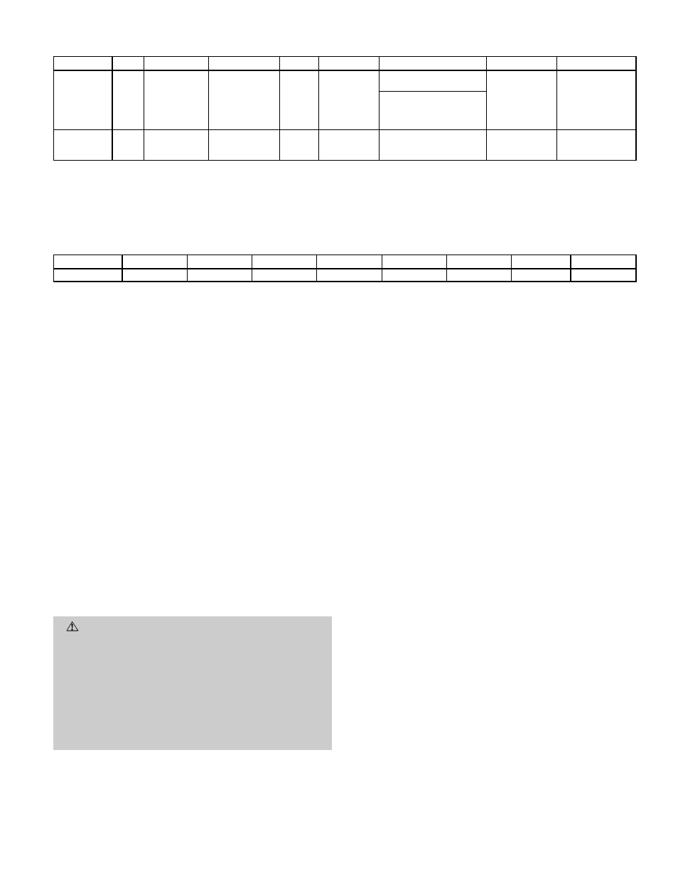
Table 4 — DIP Switch Configuration
SETTING
1
2
3
4
5
6
7
8
OPEN
—
—
Expansion
Board
Operation
Field
Test
ON
Modulated
Power
Exhaust
Time Guard
ா
Override ON
Gas Heat
Heat Pump
Operation
IN CONJUNCTION
WITH FIELD TEST —
Set Minimum
Damper Position
CLOSED
CV
Thermostat
Used
Base Control
Board Only
Field
Test
OFF
CV
Power
Exhaust
Time Guard
Override OFF
Electric Heat
Air Conditioner
Operation
LEGEND
CV — Constant Volume
NOTES:
1. The OPEN side of the DIP switch is marked ‘‘OPEN.’’ When the rocker
switch is on the ‘‘OPEN’’ side of the switch, the switch is open.
2. When the unit is being field-tested (DIP switch 4 to OPEN), the func-
tion of DIP switch 6 changes and it is used to set the minimum damper
position.
Table 5 — DIP Switch Factory Settings
UNIT
1
2
3
4
5
6
7
8
580G,H
Closed
Closed
Closed
Closed
Closed
Closed
Open
Closed
• DIP switch 6 configures the Time Guard override and,
when used with the field test function, sets the mini-
mum damper position
• DIP switch 7 configures the unit for gas heat or elec-
tric heat
• DIP switch 8 configures the unit for heat pump or
air conditioner operation
10. Adjust economizer. Check that outdoor-air damper is
closed and return-air damper is open.
IMPORTANT:
Unit power must be on for 24 hours prior to
start-up. Otherwise, damage to compressor may result.
11. The optional non-modulating power exhaust is a two-
stage design where the operation of the exhaust fans
is linked to economizer position. When the supply fan
is running and the economizer is 25% open, the base
module closes contacts, activating 2 exhaust fans. When
the economizer position reaches 75% open, the base mod-
ule activates the other 2 exhaust fans. The fans will
turn off when the economizer closes below the same
points.
START-UP
I. COOLING SECTION START-UP AND ADJUSTMENTS
CAUTION:
Complete the required procedures given
in the Pre-Start-Up section on page 20 before starting
the unit.
Do not jumper any safety devices when operating the
unit.
Do not operate the compressor when the outdoor tem-
perature is below 40 F (unless accessory low ambient
kit is installed).
Do not rapid-cycle the compressor. Allow 5 minutes
between ‘‘on’’ cycles to prevent compressor damage.
A. Checking Cooling Control Operation
Start and check the unit for proper cooling control operation
as follows:
Place SYSTEM switch in COOL position and FAN switch in
AUTO. position. Set cooling control below room temperature.
Observe that compressor, condenser fan motor, and evapora-
tor blower motors start. Observe that cooling cycle shuts down
when control setting is satisfied.
B. Cooling Sequence of Operation
On power up, the control module will activate the initializa-
tion software. The initialization software reads DIP switch
no. 1 to determine it is in the closed position. Next, DIP switch
no. 2 is read to determine it is closed for thermostat opera-
tion. The initialization sequence clears all alarms and alerts;
re-maps the input/output database for operation; sets maxi-
mum heat stages to 2; and sets maximum cool stages to 3.
Power up takes a random 1 to 63 seconds plus 5 minutes.
The TSTAT function performs a thermostat based control by
monitoring Y1, Y2, W1, W2 and G inputs. These functions
control stages: cool1, cool2, heat1, heat2 and the indoor fan,
respectively.
The control module will operate economizer and run diagnos-
tics to monitor alarms at all times.
If the thermostat energizes the G input, the control module
will turn on the indoor fan and open the economizer dampers
to minimum position. If thermostats are used to deenergize
the G input, the control module will turn off the indoor fan
and close the economizer dampers.
When cooling, G must be energized before cooling can oper-
ate. The control module determines if outdoor conditions are
suitable for economizer cooling. For the economizer to func-
tion for outside air cooling: the enthalpy must be below the
enthalpy set point; the outdoor-air temperature must be equal
to or less than 65 F; the SAT (supply-air temperature) ther-
mistor must not be in alarm; and the outdoor air reading is
available. When these conditions are satisfied, the control mod-
ule will use economizer as the first stage of cooling.
When Y1 input is energized, the economizer will be modu-
lated to maintain SAT at the set point temperature. The
default is 55 F. When SAT is above the set point, the econo-
mizer will be 100% open. When SAT is below the set point,
the economizer will modulate between minimum and 100%
open position. When Y2 is energized, the control module will
turn on compressor 1 and continue to modulate the econo-
mizer as described above. If the Y2 remains energized and
the SAT reading remains above the set point for 15 minutes,
—21—