1116fm (angle) - pressure relief valve, Maintenance, Disassembly/assembly – Watts 1116FM User Manual
Page 3
Valve Size
150 Outlet
300 Outlet
150 Inlet
300 Inlet
150 Inlet
300 Inlet
A
A
B
B
C
D
D
E
F
in.
mm
in.
mm
in.
mm
in.
mm
in.
mm
in.
mm
in.
mm
in.
mm
in.
mm
in.
mm
3
80
5
3
⁄
4
146
6
1
⁄
8
156
5
3
⁄
4
146
6
1
⁄
8
156
5
1
⁄
2
140
17
1
⁄
2
445
17
3
⁄
4
451
9
1
⁄
2
241
7
7
⁄
8
200
4
100
6
3
⁄
4
171
7
1
⁄
8
181
6
3
⁄
4
171
7
1
⁄
8
181
5
1
⁄
2
140
19
1
⁄
4
489
19
5
⁄
8
498
10
254
9
15
⁄
16
252
6
150
8
1
⁄
2
216
8
15
⁄
16
227
8
1
⁄
2
216
8
15
⁄
16
227
4
102
24
1
⁄
2
622
25
635
11
279
13
1
⁄
4
337
8
800
11
279
11
1
⁄
2
292
11
279
11
1
⁄
2
292
4
102
26
3
⁄
4
679
27
1
⁄
4
692
13
330
16
406
USA: • Tel. (713) 943-0688 • (713) 944-9445 • www.watts.com
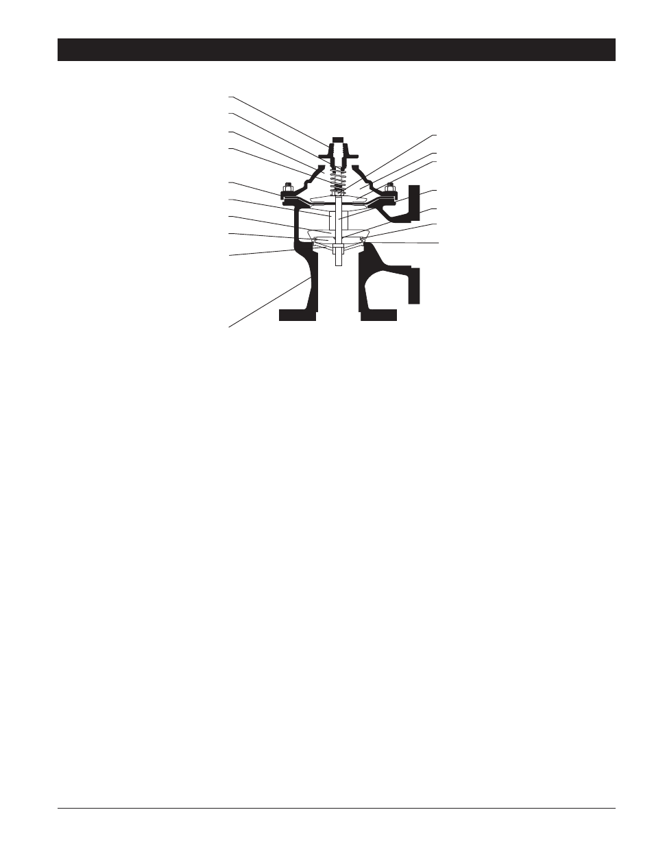
1116FM (Angle) - Pressure Relief Valve
Cover
Cover bearing
Cover chamber
Spring
Diaphragm
Stem
Spacer
Retainer
Quad seal
retainer plate
Quad seal
Seat
Seat O-ring
Body
Stem O-ring
Diaphragm
Washer
Stem nut
Maintenance
The basic valve normally requires a minimum of maintenance, due
to a packless construction and no required lubrication. However,
it is suggested that a periodic inspection schedule be established
to determine how the fluid is affecting the efficiency of the valve.
Fluid velocity as well as any substance entrained in the fluid, such
as dissolved minerals and/or suspended particles, vary between
installations. In areas subject to freezing, remove the body cover
drain plugs for winter drain-down.
NOTICE: The following method will determine if there is a dam-
aged diaphragm without removing the valve cover. Put pres-
sure into the valve and close all control lines to the valve cover
chamber.Remove a fitting on the valve cover. If there is a con-
tinuous flow out of the cover chamber through this opening, the
diaphragm is damaged or the diaphragm assembly on the stem
is loose.
CAUTION: The valve will be wide open during this pro-
cedure.Omit if the fully open valve could result in system damage.
Disassembly/Assembly
Inspection or maintenance can be accomplished without removal
from the line.
To replace the diaphragm and/or the quad ring:
1. Remove fitting nuts where necessary to release the valve
cover from the controls or control lines.
2. Remove the cover and spring.
3. Remove the diaphragm and stem assembly, taking care not
to damage the diaphragm when removing over studs.
4. With the assembly removed, examine the diaphragm and
quad ring for wear or damage. Do not disassemble unless
replacement is indicated.
5. To replace the diaphragm, quad ring and/or stem O-ring,
hold the stem in a vise or with wrench on the flats at the
bottom end of the stem. Remove the nuts.
6. Remove the diaphragm washer, diaphragm, etc., in the
proper sequence.
7. Check all surfaces, seat, O-ring grooves and diaphragm
clamping surfaces for damage and/or foreign particles.
8. To reassemble, reverse the order of disassembly. Tighten
stem nuts securely to ensure proper clamping of the dia-
phragm. To assure positive and even clamping of the dia-
phragm between the body and the cover, gradually tighten
the cover nuts diametrically opposite each other.