1116fm (angle) - pressure relief valve, Dimensions - acv 1116fm (angle), Installation and start-up – Watts 1116FM User Manual
Page 2: 125 by: checked by: revision: supercedes, Bd e a
300
0
60
30
240
270
90
120 150
210
180
INLET
150 LB FLANGE
OUTLET
150 LB FLANGE
Ш7.875"
Ш9.968"
Ш13.25"
Ш16.00"
150 LB FLANGE
INLET
5 3/4"
6 3/4"
8 1/2"
INLET
17 1/2"
26 3/4"
24 1/2"
19 1/4"
8 200
6 150
4 100
3 80
17 3/4"
19 5/8"
27 1/4"
25"
11"
150 LB FLANGE
INLET
INCH - MM
VALVE SIZE
A
300 LB FLANGE
A
B
INLET
INLET
5 3/4"
6 3/4"
8 1/2"
6 1/8"
7 1/8"
11 1/2"
8 15/16"
11"
11 1/2"
8 15/16"
7 1/8"
6 1/8"
150 LB FLANGE
300 LB FLANGE
B
C
INLET
300 LB FLANGE
C
D
5 1/4"
5 1/2"
4"
13"
9 1/2"
9 1/2"
11"
4"
E
F
TOP
VIEW
6 INCH ANGLE
150 LB BY 150 LB
XXXX
WA
TTS
XX
X
AC
V
TITLE:
DRAWING NUMBER:
NAME:
DATE:
DESIGN BY:
DRAWN BY:
CHECKED BY:
APPROVED BY:
REVISIONS:
DATE:
TOLERANCES:
EXCEPT
AS
NOTED
FRACTIONAL
ANGULAR
DECIMAL
.XX DIMS
.XXX DIMS
.XXXX DIMS
SCALE
SURFACE
EXCEPT
AS
NOTED
+
+
+
+
+
1/64
1/2°
.01
.005
.001
125
BY:
CHECKED BY:
REVISION:
SUPERCEDES:
CONTROL
VALVE
AUTOMATIC
HOUSTON, TEXAS
WATTS AUTOMATIC CONTROL VALVE COMPANY
B
D
E
A
Ш13.25"
Ш9.968"
Ш13.25"
Ш16.00"
8 1/2"
6 3/4"
8 1/2"
26 3/4"
24 1/2"
24 1/2"
19 1/4"
8 800
8 200
6 150
4 100
25"
19 5/8"
27 1/4"
25"
11"
6 3/4"
8 1/2"
8 1/2"
7 1/8"
11 1/2"
8 15/16"
8 15/16"
11"
11 1/2"
8 15/16"
8 15/16"
7 1/8"
5 1/2"
13"
4"
9 1/2"
11"
11"
4"
4"
F
C
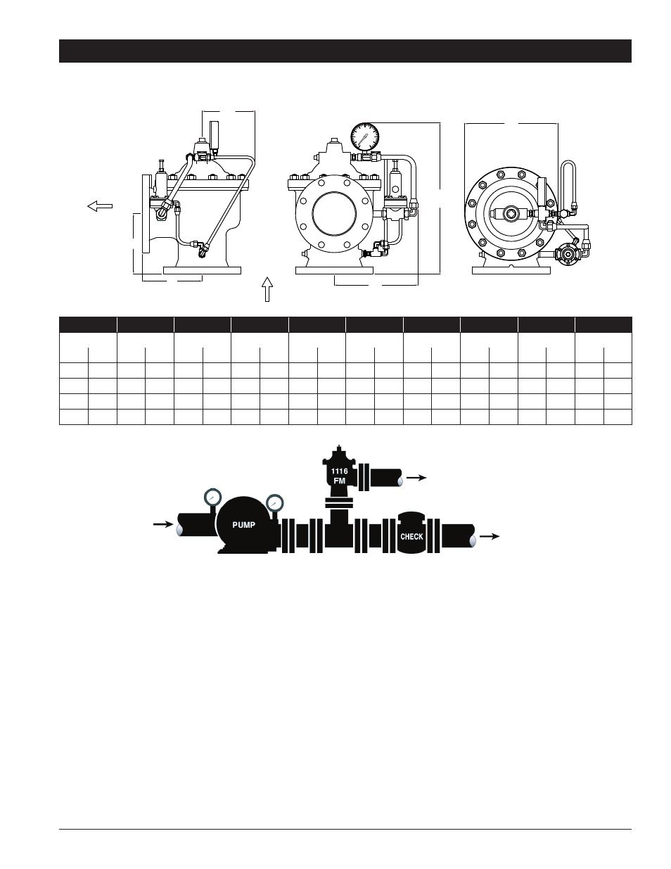
DIMENSIONS - ACV 1116FM (Angle)
TO FIRE
PROTECTION
SYTEM
TO WASTE CONE
SUPPLY
FIRE PUMP RELIEF VALVE
Valve Size
150 Outlet
300 Outlet
150 Inlet
300 Inlet
150 Inlet
300 Inlet
A
A
B
B
C
D
D
E
F
in.
mm
in.
mm
in.
mm
in.
mm
in.
mm
in.
mm
in.
mm
in.
mm
in.
mm
in.
mm
3
80
5
3
⁄
4
146
6
1
⁄
8
156
5
3
⁄
4
146
6
1
⁄
8
156
5
1
⁄
2
140
17
1
⁄
2
445
17
3
⁄
4
451
9
1
⁄
2
241
7
7
⁄
8
200
4
100
6
3
⁄
4
171
7
1
⁄
8
181
6
3
⁄
4
171
7
1
⁄
8
181
5
1
⁄
2
140
19
1
⁄
4
489
19
5
⁄
8
498
10
254
9
15
⁄
16
252
6
150
8
1
⁄
2
216
8
15
⁄
16
227
8
1
⁄
2
216
8
15
⁄
16
227
4
102
24
1
⁄
2
622
25
635
11
279
13
1
⁄
4
337
8
800
11
279
11
1
⁄
2
292
11
279
11
1
⁄
2
292
4
102
26
3
⁄
4
679
27
1
⁄
4
692
13
330
16
406
USA: • Tel. (713) 943-0688 • (713) 944-9445 • www.watts.com
1116FM (Angle) - Pressure Relief Valve
Installation and Start-up
Start-up of an Automatic Control Valve requires following proper procedures. Time must be allowed for the valve to react
to adjustments and the system to stabilize. The objective is to bring the valve into service in a controlled manner to protect
the system from damaging overpressure.
NOTICE: Avoid mounting valves in a vertical discharge postion (valve stem horizontal or cover pointed sideways.) Valves mounted in
this position may not perform as tested and approved.
•
Clear the line of slag and other debris.
•
Install the valve so that the FLOW ARROW marked on the valve body matches the flow through the line.
•
Install pressure gauge (supplied) in the fitting on valve tubing.
1. Turn the Relief Control adjustment screw counterclockwise (out). This lowers the initial relief set-point, allowing the set-point to be
increased to the desired setting.
2. Loosen a tube fitting at a high point on the valve. This allows the cover to vent trapped air during initial filling of the valve.
3. Start the pump to supply fluid/pressure to the valve.
4. Tighten the tubing when all air is vented from the cover as indicated by continual flow of fluid.
NOTICE: THE RELIEF SET-POINT SHOULD BE LOWER THAN DESIRED AT THIS TIME.
5. Turn the Relief Control adjustment screw clockwise (in) slowly, allowing time for the pressure to gradually increase to the desired
set-point.