How it operates, Basic installation instructions watts – Watts LF909 User Manual
Page 2
1. Backflow preventers must be installed in high-visibility locations
in order to allow for immediate notice of telltale discharge or
other malfunction. This location should also facilitate testing and
servicing, and protect against freezing and vandalism.
2. Installing a backflow preventer in a pit or vault is not recom-
mended as flooding of the pit will cause a crossconnection.
Ensure that
all local codes and required safety provisions
are met. An air gap below the relief port must be maintained so
as to avoid, flooding and submersion of the assembly, which
may lead to a cross-connection.
3. A strainer should be installed ahead of the backflow preventer to
protect all internal components from unnecessary fouling.
CAUTION
!
Do not install a strainer ahead of the backflow preventer on seldom-
used, emergency water lines (i.e. fire sprinkler lines). The strainer
mesh could potentially become clogged with debris present in the
water and cause water blockage during an emergency.
4. Normal discharge and nuisance spitting are accommodated by
the use of a Watts air gap fitting and a fabricated indirect waste
line. Floor drains of the same size
MUST be provided in case of
excessive discharge.
5. When a 909 and LF909 Series backflow preventer is installed for
dead-end service applications (i.e. boiler feed lines, cooling
tower makeup or other equipment with periodic flow require-
ments), discharge from the relief vent may occur due to water
supply pressure fluctuation during static no-flow conditions. A
check valve may be required ahead of the backflow preventer.
*Please see “Troubleshooting”, page 7,
prior to installation.
6. The 909 and LF909 Series backflow preventer is designed so
that the critical level of the relief valve is positioned below the
first check. This unique feature allows the valve to be
installed
either vertically or horizontally.
7.
Installation procedures must comply with all state and
local codes. *Please see page 3 for specific installation proce-
dures.
8. Prior to installation, thoroughly flush all pipe lines to remove any
foreign matter.
9.
Start up at Initial Installations and After Servicing: The down-
stream shutoff should be closed. Slowly open upstream shutoff
and allow the backflow preventer to fill slowly. Bleed air at each
test cock. When backflow preventer is filled, slowly open the
downstream shutoff and fill the water supply system. This is nec-
essary to avoid dislodging O-rings or causing damage to internal
components.
10.
Test: The 909 and LF909 Series backflow preventer must be
tested by a certified tester at the time of installation in order to
ascertain that the assembly is in full working order and may be
relied upon to protect the safe drinking water as per applicable
standards.
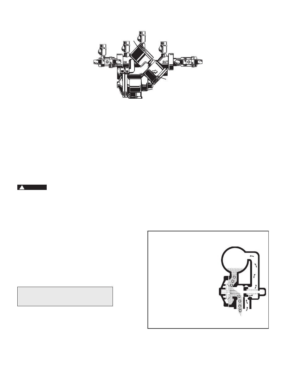
First
Check
Relief
Valve
Second
Check
909QT/LF909QT
How It Operates
The unique relief valve
construction incorporates two
channels: one for air, one for
water. When the relief valve
opens, as in the accompanying
air-in/water-out diagram, the
right hand channel admits air to
the top of the reduced pressure
zone, relieving the zone vacuum.
The channel on the left then
drains the zone to atmosphere.
Therefore, if both check valves
foul, and simultaneous negative
supply and positive backpressure
develops, the relief valve uses the
air-in/water-out principle to stop
potential backflow.
Reduced
Pressure
Zone
Water Out
Air In
2
Basic Installation Instructions
Watts
3
⁄
4
" – 2" (20-50mm) 909QT/LF909QT High Capacity Relief Series:
Location and Installation Considerations
For repair kits and parts, refer to our Backflow
Prevention Products Repair Kits & Service Parts
price list PL-RP-BPD found on
www.watts.com.