Iv. replacement parts list, V. membrane replacement, Vi. appendix – Watts PWRO440 User Manual
Page 7: Temperature correction factors
7
DescRiPtiOn
Prefilter, 5 micron, melt blown
RO membrane, low energy
Prefilter pressure gauge 0 – 100psi
Pump discharge pressure gauge 0 – 300psi
Product flow meter 0.5 – 5 gpm
Reject flow meter with valve 0.5 – 5 gpm
Water quality meter
Pump & motor 0.75 HP for PWRO4401
Pump & motor 1.0 HP for PWRO4402
Pump & motor 1.5 HP for PWRO4403
Controller with on/off switch
Low pressure switch, ¼" MPT
Recycle needle valve PVC
Inlet solenoid valve, 1", 24 volt coil
Pressure vessel with end caps, 316 SS
IV. Replacement Parts List
A list of common replacement parts is provided below. Contact your
Watts representative for replacement parts assistance.
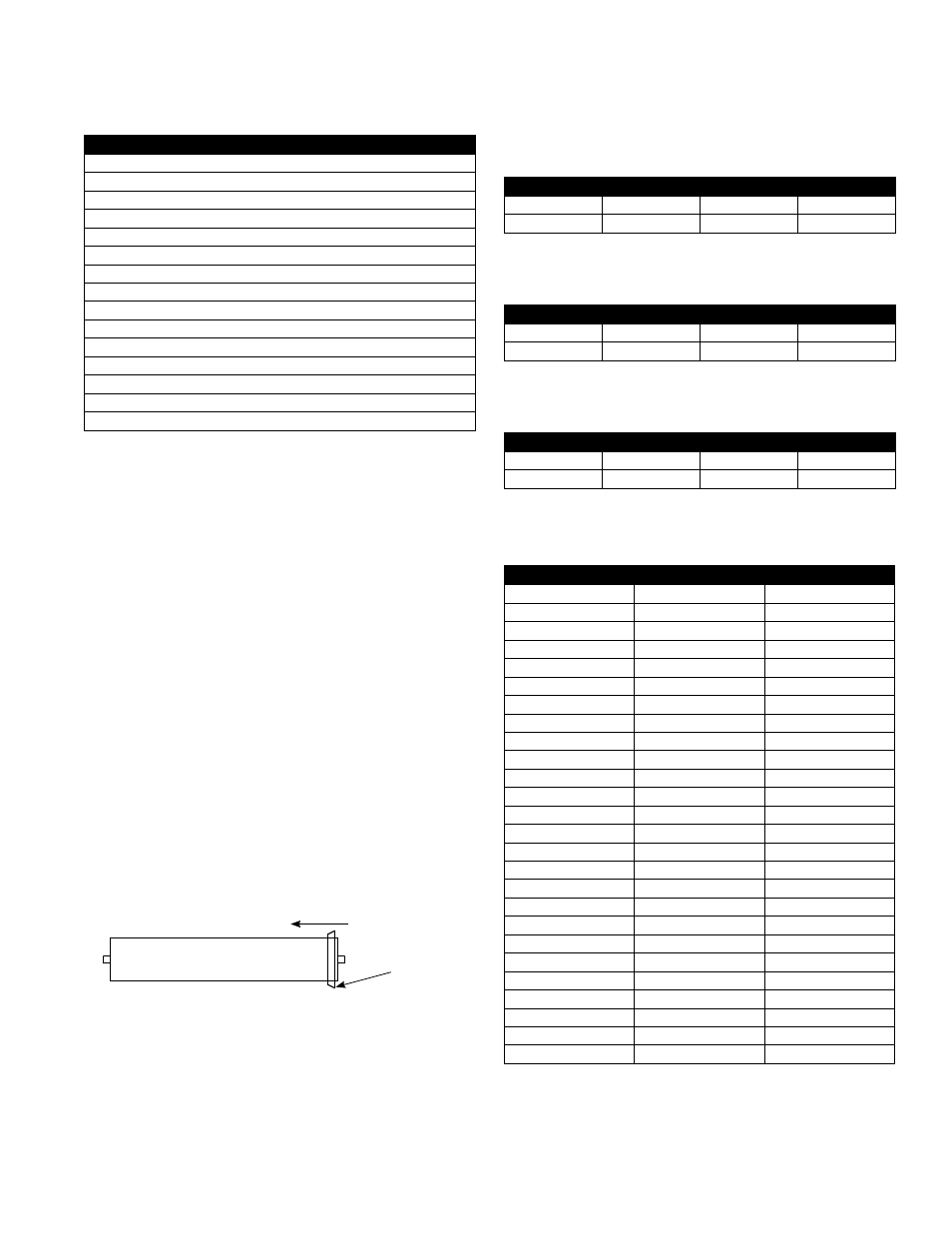
V. Membrane Replacement
1. Turn off the system and close the feed water shutoff valve.
2. Unplug the unit.
3. Disconnect the tubing from the top of the membrane housing(s).
4. Loosen the clamps and remove the top end cap(s).
5. Remove the old membrane(s) by pulling them up and out of the
housings. You may need to grab the old by the membrane with
a pair of pliers.
6. Install the new membrane(s) in the housing(s) and replace the
end caps. The new membranes should be installed in the same
orientation as the old membranes.
Note: It is very important that the brine seal does not flip up or roll
when installing the membrane brine seal first. Use plenty of glycerin
lubricant and use a gentle twisting / rocking motion as you slide the
membrane in. If you are unable to install the membrane brine seal
first without rolling the seal then lay the unit over, remove the bottom
end cap, and install the membrane brine seal last.
7. Reconnect the tubing to the bottom of the membrane
housing(s).
8. Follow the start up procedure in section III-D.
Brine
Seal
Flow Direction
Membrane
°c
°F
cORRectiOn FactOR
30
86
1.16
29
84.2
1.13
28
82.4
1.09
27
80.6
1.06
26
78.8
1.03
25
77
1.00
24
75.2
0.97
23
73.4
0.94
22
71.6
0.92
21
69.8
0.89
20
68
0.86
19
66.2
0.84
18
64.4
0.81
17
62.6
0.79
16
60.8
0.77
15
59
0.74
14
57.2
0.72
13
55.4
0.70
12
53.6
0.68
11
51.8
0.66
10
50
0.64
9
48.2
0.62
8
46.4
0.61
7
44.6
0.59
6
42.8
0.57
5
41
0.55
Multiply the nominal product flow at 25°C by the temperature correction factor to
determine the flow at various other temperatures.
VI. Appendix
The following tables are intended as a guide to determining the flow
rates for the PWRO440 Series RO systems. All flows are in gallons
per minute (GPM) with 77°F feed water.
Nominal flows for systems operating at 50% recovery with a
feed water SDI < 1.
Nominal flows for systems operating at 50% recovery with a
feed water SDI < 3.
Nominal flows for systems operating at 50% recovery with a
feed water SDI < 5.
MODEL NUMBER
PWRO4401
PWRO4402
PWRO4403
Product GPM
1.5
3.0
4.5
Reject GPM
1.5
3.0
4.5
MODEL NUMBER
PWRO4401
PWRO4402
PWRO4403
Product GPM
1.25
2.5
3.75
Reject GPM
1.25
2.5
3.75
MODEL NUMBER
PWRO4401
PWRO4402
PWRO4403
Product GPM
1
2
3
Reject GPM
1
2
3
Temperature Correction Factors