Ii. controls, indicators, and components, Iii. operation, A. installation – Watts PWRO440 User Manual
Page 3: B. plumbing connections
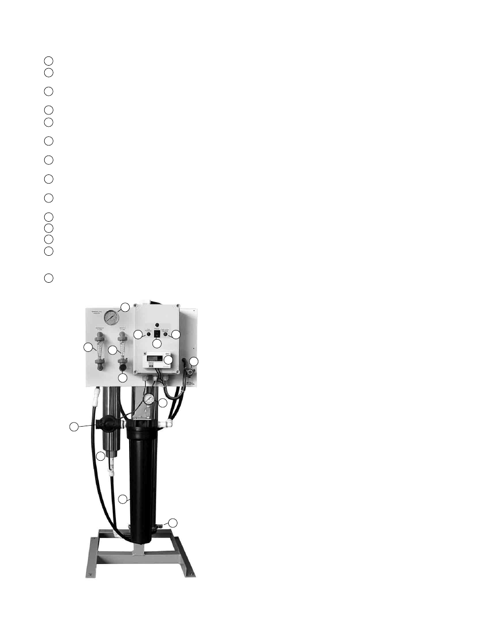
II. Controls, Indicators, and
Components
(See Figure 1)
A On / Off Switch – Turns the unit on and off.
B Low-pressure indicator – Turns on when low pump inlet pres-
sure is detected.
C Tank full / Interlock indicator – Turns on when the unit is shut
down due to high tank or pretreatment interlock.
D Reject Control Valve - Controls the amount of reject flow.
E Reject Recycle Control Valve – Controls the amount of recycle
flow.
F Prefilter Outlet Pressure Gauge - Indicate the outlet pressures of
the prefilter.
G Pump Discharge Pressure Gauge - Indicates the membrane
feed pressure.
H Reject Flow Meter - Indicates the reject flow rate in gallons per
minute (gpm).
I Product Flow Meter - Indicates the product flow rate in gallons
per minute (gpm).
J Prefilter Housing - Contains the RO prefilter.
K RO Feed Pump - Pressurizes the RO feed water.
L RO Membrane Housing(s) - Contains the RO membrane(s).
M Water Quality Meter – Indicates the quality of the feed and prod-
uct water in parts per million of total dissolved solids
(PPM – TDS).
N Feed Water Inlet.
III. Operation
A. Installation
1. Proper pretreatment must be determined and installed prior to
the RO system.
2. The water supply and pretreatment equipment should be suf-
ficient to provide a minimum of 10-psig at the maximum feed
flow.
3. An electrical disconnect switch located within 10 feet of the unit
is recommended.
4. Responsibility for meeting local electrical and plumbing codes
lies with the owner / operator.
5. Install indoors in an area protected from freezing and direct sun-
light. Space allowances for the removal of the membranes from
the pressure vessels should be provided.
6. Verify that a prefilter cartridge is installed in the housing.
(see Figure #1, Item J).
B. Plumbing Connections
Note: It is the responsibility of the end user to ensure that the
installation is done according to local codes and regulations.
1. Connect the pretreated feed water line to the prefilter inlet
(Figure # 1 Item N). A feed water shutoff valve should be located
within 10 feet of the system.
2. Temporarily connect the product water outlet to a drain. The
product outlet is located behind the panel at the top of the
product flow meter. The product water line should never be
restricted. Membrane and/or system damage may occur if the
product line is blocked.
3. Connect the reject water outlet to a drain. The reject outlet is
located behind the panel at the top of the reject flow meter. The
reject drain line should never be restricted. Membrane and/or
system damage may occur if the reject drain line is blocked. An
air gap must be located between the end of the drain line and
the drain. The use of a standpipe or other open drain satisfies
most state and local codes and allows for visual inspection and
sampling.
3
Figure 1
G
I
H
D
N
K
J
L
F
B
A
C
E
M