C. electrical, Pwro440 deluxe controller d. startup, E. control function – Watts PWRO440 User Manual
Page 4
4
C. Electrical
Note: It is the responsibility of the end user to ensure that the
installation is done according to local codes and regulations.
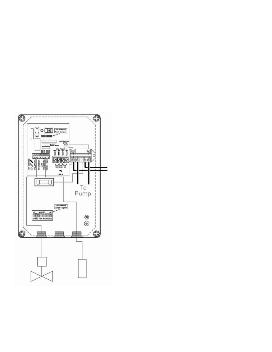
1. Make sure the on / off switch is in the off position (Figure # 1
item A).
2. Wire the common side of the motor starter to the incoming
power.
3. Connect the incoming power supply to the contactor terminals
as shown.
4. Optional - remove the jumpers and connect the high tank level
switch and / or the pretreatment lock out switch to the control-
ler terminal strip. These should be normally closed dry contacts
only (do not apply power to these terminals). When the circuit
between the two terminals is complete, the RO will run. When
the circuit is open the RO will shut down and the light on the
front of the controller will turn on.
PWRO440 Deluxe Controller
D. Startup
1. Verify that the pretreatment equipment is installed and working
properly. Verify that no free chlorine is present in the feed water.
2. Verify that the on / off switch is in the off position.
3. Verify that a filter cartridge is installed in the prefilter housing.
4. Open the reject control valve completely (Figure # 1 item D) by
turning it counterclockwise.
5. Close the reject recycle control valve (Figure # 1 item E) com-
pletely by turning it clockwise.
6. Open the feed water shutoff valve installed in step III-B-1 above.
7. Move the controller on/off switch to the on position.
8. Allow the unit to run for 15 – 30 minutes to flush the preservative
from the membrane(s).
9. Adjust the reject control valves (Figure # 1 items D & E) until the
desired flows are achieved. Closing the reject valve increases
the product flow and decreases the reject flow. Opening the
reject recycle valve decreases both the reject and product flow.
See the flow rate guidelines and temperature correction table in
the appendix to determine the flow rates for different operating
temperatures.
10. Allow the product water to flow to drain for 30 minutes.
11. Turn off the system and connect the product water line to the
point of use. The product water line should never be restricted.
Membrane and/or system damage may occur if the product
water line is blocked.
12. Restart the system and record the initial operating data using the
log sheet.
E. Control Function
1. When the power switch is turned on, the pump will run as long
as the circuit between the tank level terminals and the interlock
terminals are closed. The RO pump and inlet valve will turn on
when the level switch contacts are closed (tank not full). The RO
pump and inlet valve will turn off if the level switch contacts open
(tank full) or the pretreatment interlock contacts open.
2. If the pump suction pressure drops below the pressure switch
set point (3 – 5psi) for five (5) seconds, the RO pump and inlet
valve will turn off. A red light on the front of the controller will turn
on to indicate that the unit has shutdown due to low pressure.
Turn the controller off and back on to reset the unit. The control-
ler will automatically reset after 30 minutes. The reset time can
be adjusted by moving the jumper cap inside the controller.
3. Quality Meter – The quality meter measures the feed water and
product water total dissolved solids (TDS) in parts per million
(PPM). The lower the TDS the more pure the water is. To check
the TDS press the power button, then press either the IN or
OUT button. The IN button checks the feed water TDS and the
OUT button checks the product water TDS. The meter will auto-
matically turn itself off after a few seconds. The quality meter is
powered by two AAA batteries. To replace the batteries, lift the
meter out of the bracket and remove the back cover.
Figure 2
Inlet Valve
LP Switch
230V
1-Phase
Power Inlet