Watts LF909 User Manual
Basic installation instructions
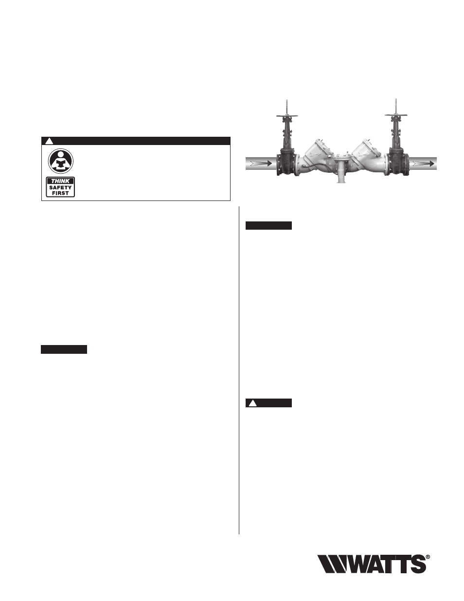
RP/IS-909/909RPDA
Watts 909 OSY shown
Designed for inline servicing
IMPORTANT:
Inquire with governing authorities for local installa-
tion requirements.
NOTICE
For Australia and New Zealand, line strainers should be installed
between the upstream shutoff valve and the inlet of the backflow pre-
venter.
Its important that this device be tested periodically in compliance
with local codes, but at least once per year or more as service con-
ditions warrant. If installed on a fire sprinkler system, all mechanical
checks, such as alarm checks and backflow preventers, should be
flow tested and inspected internally in accordance with NFPA 13
and NFPA 25.
Testing
For field testing procedure, send for IS-TK-DL,
IS-TK-9A, IS-TK-99E and IS-TK-99D.
For repair kits and service parts, reference PL-RP-BPD at
www.watts.com
For technical assistance, contact your local Watts
representative.
Installation, Maintenance, & Repair
Series 909, LF909, 909RPDA, LF909RPDA
Reduced Pressure Zone Assemblies
Reduced Pressure Detector Assemblies
Sizes: 2
1
⁄
2
" – 10" (65 – 250mm)
Local building or plumbing codes may require modifications to
the information provided. You are required to consult the local
building and plumbing codes prior to installation. If this informa-
tion is not consistent with local building or plumbing codes, the
local codes should be followed.
Need for Periodic Inspection/Maintenance: This product
must be tested periodically in compliance with local codes, but
at least once per year or more as service conditions warrant.
Corrosive water conditions, and/or unauthorized adjustments
or repair could render the product ineffective for the service in-
tended. Regular checking and cleaning of the product’s internal
components helps assure maximum life and proper product
function.
WARNING
!
Read this Manual BEFORE using this equipment.
Failure to read and follow all safety and use information
can result in death, serious personal injury, property
damage, or damage to the equipment.
Keep this Manual for future reference.
Basic Installation Instructions
NOTICE
The flange gasket bolts for the gate valves should be re tight ened
during in stal la tion as the bolts may have loos ened due to stor age
and ship ping.
High Capacity Relief Series:
Location and Installation Considerations
1. Backflow preventers must be installed in high-visibility locations
in order to allow for immediate notice of telltale discharge or
other malfunction. This location should also facilitate testing and
ser vic ing, and protect against freezing and vandalism.
2. Installing a backflow preventer in a pit or vault is not rec om-
mend ed. However, if this becomes necessary, Watts highly rec-
om mends that a licensed journeyman tradesperson, who is rec-
ognized by the authority having jurisdiction, be consulted to
ensure that all local codes and required safety provisions are
met. An air gap below the relief port must be maintained so as
to avoid flooding and submersion of the assembly, which may
lead to a cross connection. *Please refer to Figure No. 1 for fur-
ther information.
3. A strainer should be installed ahead of the backflow preventer to
protect all internal components from unnecessary fouling.
CAUTION
!
Do not install a strainer ahead of the backflow preventer on seldom-
used, emergency water lines (i.e. fire sprinkler lines). The strainer
mesh could potentially become clogged with debris present in the
water and cause water blockage during an emer gen cy.
4. Normal discharge and nuisance spitting are accommodated by
the use of a Watts air gap fitting and a fabricated indirect waste
line. Floor drains of the same size MUST be provided in case of
excessive discharge. *Please refer to Figure No. 1 and Figure
No. 2 for further in for ma tion.
5. When a 909/LF909 Series backflow preventer is installed for
dead-end service applications. (i.e. boiler feed lines, cooling
tower makeup or other equip ment with periodic flow require-
ments), discharge from the relief vent may occur due to water
supply pressure fluctuation during static no-flow con di tions. A
check valve may be required ahead of the backflow preventer.
*Please see “Troubleshooting”, Page 7, prior to installation.