Lassic, Eries, Headloss – Watts F1110-14 User Manual
Page 3: Cavitation chart
8550 Hansen Road
•
Houston, Texas 77075
•
(Ph) 713.943.0688
•
(Fx) 713.944.9445
•
www.watts.com
C
laSSiC
S
erieS
Headloss
CAVITATION ZONE
INLET PRESSURE - PSI
OUTLET PRESSURE - PSI
300
280
260
240
220
200
180
160
140
120
100
80
60
40
20
0
10 20
40
50
60
70
80
90
130 140
120
110
100
30
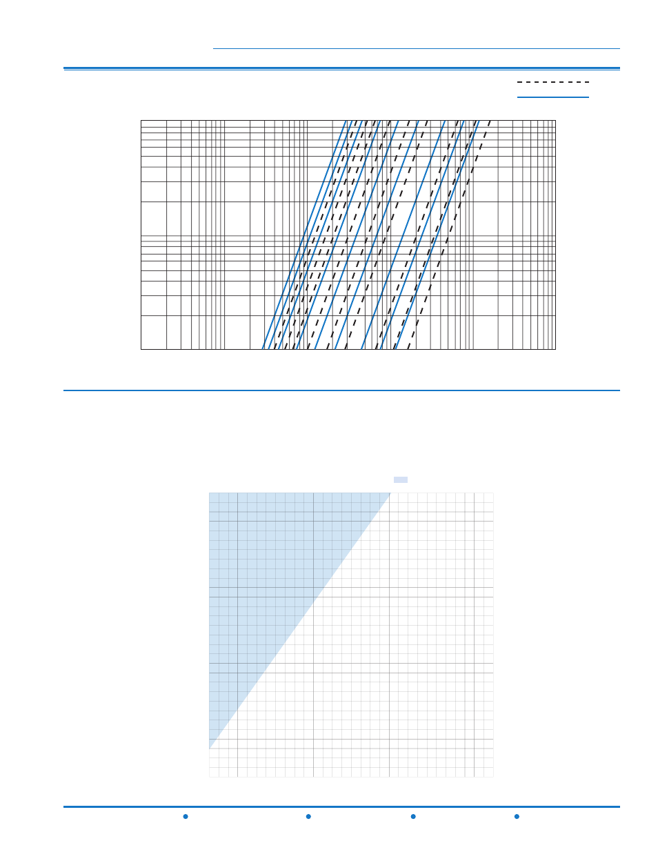
CAVITATION CHART
After selecting the valve size, locate inlet and outlet pressures on this chart. If the intersection point falls
in the shaded area, cavitation can occur. Operation of valves continually in the cavitation zone should be
avoided. Consult Watts ACV for alternatives.
Cavitation Chart
1
1/4
1
1/2
2
1/2
2
3
4
6
8
10
1
1/4
2
1/2
1
1/2
2
3
4
6
8
10
100000
20000
10000
5000
1000
500
100
50
10
5
1
1
5
10
50
100
Pr
es
su
re
D
iff
er
en
ce
p
si
Flow Rate - Gallons per minute (Water)
Globe
Angle
F110-14 (Globe)
F1110-14 (Angle)
This manual is related to the following products: