R55 color mark sensor, R55 hookup diagrams, Quick disconnect (qd) option – Banner R55E Series User Manual
Page 7: Pin euro-style pin-out, Warning ... not a safety device
page
7
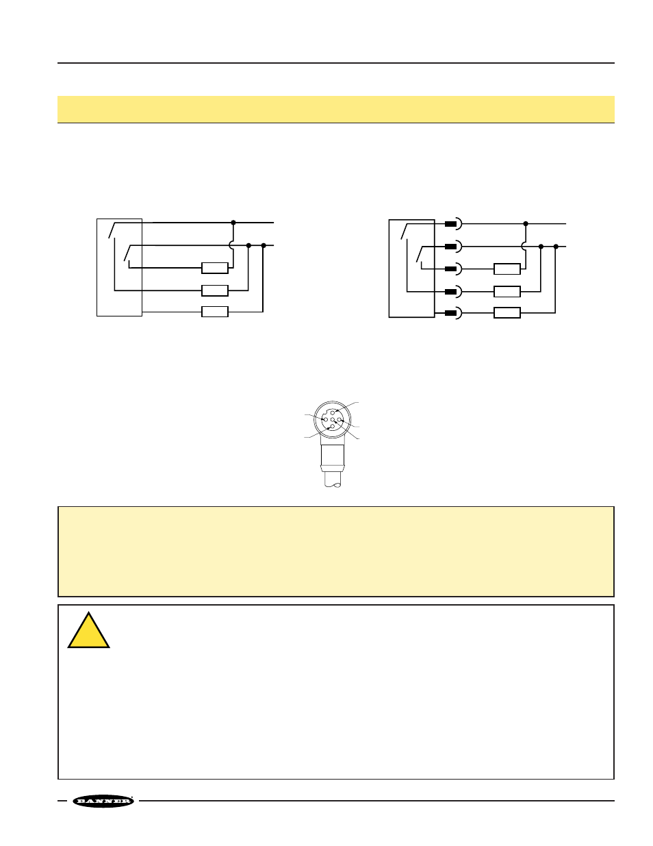
R55 Color Mark Sensor
R55 Hookup Diagrams
R55 Sensor
with Attached Cable
R55 Sensor
with Quick Disconnect
Quick Disconnect (QD) Option
R55 sensors are sold with either a 2 m (6.5') attached PVC-covered cable, with a 5-pin euro-style pigtail QD cable fitting, or with an
integral 5-pin euro QD.
R55 QD sensors are identified by the letter “Q” in their model number suffix. Mating cables for QD R55 sensors are model MQDC1-
5xx (straight connector) or MQDC1-5xxRA (right-angled connector). For more information on QD cables see following page.
5-Pin Euro-Style Pin-out
(Cable Connector Shown)
White Wire
Blue Wire
Black Wire
Brown Wire
Gray Wire
bn
wh
bu
+
–
bk
ye
Load
Load
10-30V dc
Load
0 to 10 mA
bn
wh
bu
+
–
bk
gy
Load
Load
10-30V dc
Load
0 to 10 mA
WARNING ... Not a Safety Device
These R55 photoelectric presence sensors do NOT include the self-checking redundant circuitry necessary to allow
their use in personnel safety applications. A sensor failure or malfunction can result in either an energized or a de-
energized sensor output condition.
Never use this product as a sensing device for personnel protection. Its use as a safety device may create an unsafe condition
which could lead to serious injury or death.
Only MINI-SCREEN
®
, MULTI-SCREEN
®
, MICRO-SCREEN
™
, MACHINE-GUARD
™
and PERIMETER-GUARD
™
Systems (and other
systems so designated) are designed to meet OSHA and ANSI machine safety standards for point-of-operation guarding
devices. No other Banner sensors or controls are designed to meet these standards, and they must NOT be used as sensing
devices for personnel protection.
!