Overview, Receiver indicators emitter indicators, Sensor configuration – Banner WORLD-BEAM QS30 High-Power Opposed Mode User Manual
Page 2: Sensor alignment
Overview
Banner QS30 Series high-power opposed-mode sensors are extremely rugged, powerful and leakproof. They are designed to withstand
the most demanding industrial applications, including high-pressure washdown areas. They are powerful enough to burn through heavy
fog, dust, and most types of industrial and process contamination.
The sensor’s electronics are epoxy-encapsulated for maximum resistance to mechanical shock and vibration. The popular WORLD-
BEAM-style housing provides multiple mounting configurations in a minimum of space.
The innovative circuitry used in these sensors provides the best EMI/RFI noise immunity of any non-synchronized emitter/receiver pair.
For applications where optical crosstalk between multiple sensor pairs may be a problem, the sensors provide a choice between two
frequencies (A and B). (Each emitter must be set to the same frequency as its receiver, see
on page 2.)
Light Operate and Dark Operate outputs are available, depending on the model. Each model has two outputs that switch simultaneously:
one each NPN (sinking) and PNP (sourcing).
Additional configuration options are available; contact the factory for information about the following options:
• Additional modulation frequency choices (up to four)
• Modified sensor gain
• ON-delay or OFF-delay settings
• Fixed modulation frequency models
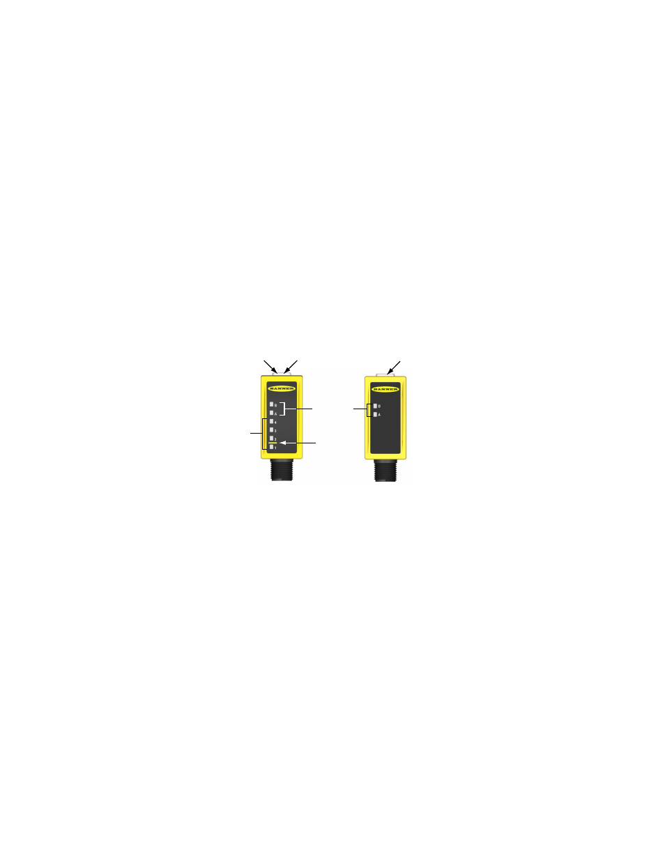
Each sensor has a green Power ON/OFF indicator and yellow indicators for the selected modulation frequency. In addition, receivers
have a yellow LED that lights when the outputs are conducting, plus a 4-element light bar that indicates signal strength, relative to the
switch point (the higher the number lit, the more light is received).
Power ON/OFF
(Green)
Power ON/OFF
(Green)
Modulation
Frequency
Selection
Indicators
Sensing
Threshold
Signal
Strength
Light Bar
Output Conducting
(Yellow)
Receiver
Indicators
Emitter
Indicators
Figure 3. Receiver and Emitter Indicators
Sensor Configuration
The modulation frequency (A or B) is selected by the state of the gray wire (on cabled models; pin 5 on QD models – see hookups...). A
“+” voltage or no connection selects frequency A; connecting it to “-” selects frequency B.
To disable (or inhibit) the emitter LED for testing the receiver, attach the white wire to “-” voltage.
Sensor Alignment
Adjust the emitter first, then the receiver. Verify that both sensors are wired for the same modulation frequency, then adjust the emitter’s
position until the receiver signal strength light bar indicates its highest amount of signal received (the highest number lit). Tighten the
emitter mounting hardware, then repeat the process for the receiver.
To achieve the best crosstalk immunity, position a single matched emitter within the receiver's field of view (15 degrees). When it is
necessary to position an alternate emitter in the receiver's field of view, sensor alignment is required to ensure the matched frequency
emitter provides the stronger signal to its receiver, and the alternate frequency emitter does not reduce the signal strength of the receiver
(as indicated by the 4-element signal strength light).
WORLD-BEAM® QS30 Series Sensors
2
www.bannerengineering.com - tel: 763-544-3164
P/N 115011 Rev. E