Micro-amp, System, Ma4l latch logic module – Banner MICRO-AMP Series User Manual
Page 13: Micro-amp ma4l specifications, Logic truth tables
N/O OUTPUT
(pin #6)
H
L
H
L
Off
L
H
L
H
On
L
L
L*
L*
On
H
L
H
On
H
L
H
On
L
H
L
Off
X
NC
NC
NC
X
NC
NC
NC
H = logic HIGH
L = logic LOW
X = either HIGH or LOW (does not matter)
= HIGH to LOW transition
= LOW to HIGH transition
NC = no change of state
RESET (pin #1)
SET (pin #2)
SET-RESET LATCH MODE
(no connections to INPUT or INHIBIT)
Input Polarity:
L
H
L
Off
*NOTE: both outputs
conduct in this
condition (*).
*
OUTPUT
SET
RESET
OUTPUT
(at pin #5)
INPUT
OUTPUT
INPUT
RESET
Set/reset latch mode, MA4L:
Edge-triggered latch mode, MA4L:
Flip-flop (
÷
2) logic, MA4L:
MICRO-AMP
®
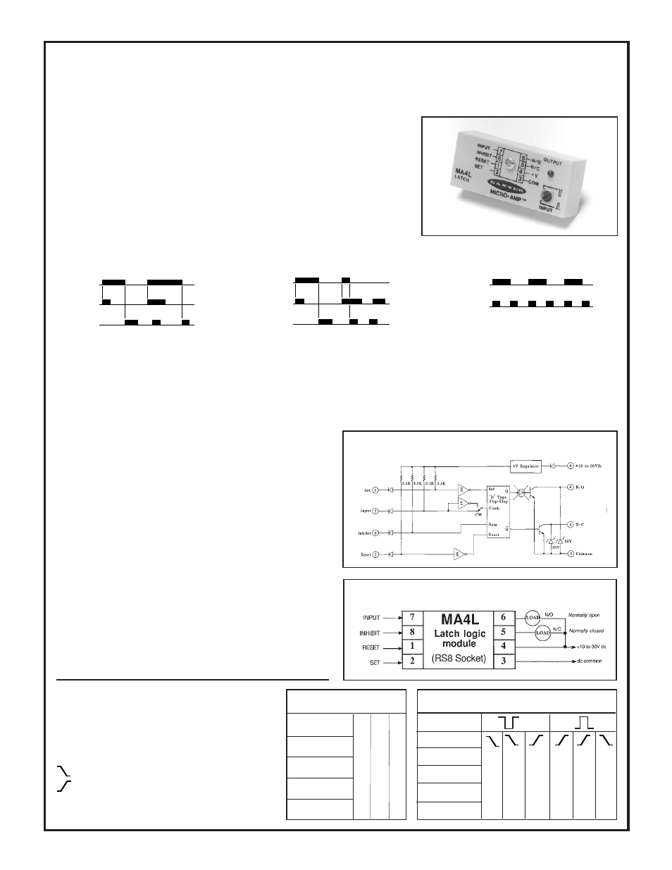
model MA4L offers two latching logic modes. It can be latched and
unlatched with low-going signals to its SET and RESET inputs. It also will function
as an edge-triggered "D" flip-flop latch when signals are presented to its INPUT pin.
The edge-triggered latch may be interrogated with a second signal at the INHIBIT
or the RESET pin. In this mode, the MA4L is very useful in inspection/rejection
applications. The MA4L may also be wired for alternate-action divide-by-two logic
(see logic diagram, below).
The MA4L directly accepts the outputs of other Banner MICRO-AMP modules plus
the NPN (current sinking) output of self-contained dc sensors.
SUPPLY VOLTAGE: 10 to 30V dc at less than 20 milliamps
(exclusive of load); 10% maximum ripple.
INPUTS: INPUT, INHIBIT, RESET, and SET signals are buffered
for 1-millisecond response. A logic "low" must be less than 2V dc. A
logic "high" is at least 6V dc or an open circuit. Inputs must be capable
of sinking at least 4 milliamps. Inputs may be derived from limit
switches or from dc sensors with NPN (current sinking) output
transistors. INPUT signal polarity is selectable for either high-going
or low-going transition.
OUTPUT CONFIGURATION: two open-collector NPN transis-
tors with complementary outputs (one normally open, one normally
closed). Maximum sinking current 150 milliamps, each output.
Saturation voltage less than 0.5V dc at 10 milliamps. Off-state leakage
current less than 1 microamp.
RESPONSE SPEED: all inputs will respond to a low signal or a high
signal of 1 millisecond duration or longer.
CIRCUIT PROTECTION: reverse voltage polarity protected.
Latch comes up reset after power-up.
SELECTOR SWITCH: single-turn potentiometer selects response
polarity of INPUT. Fully clockwise = high-going transition; fully
counterclockwise = low-going transition.
INDICATOR: red LED indicator on the top of the module lights
whenever the N/O output is conducting.
MICRO-AMP MA4L Specifications
CONSTRUCTION: totally encapsulated plug-in package with
molded VALOX
®
housing. Gold-flashed connection pins.
OPERATING TEMPERATURE:
0 to 70 degrees C (32 to 158 degrees F).
N/O OUTPUT
(pin #6)
N/C OUTPUT
(pin #5)
INPUT (pin #7)
Indicator LED
N/C OUTPUT
(pin #5)
Indicator LED
Hookup Diagram, MA4L LATCH Module
Functional Schematic MA4L LATCH Module
EDGE-TRIGGERED LATCH MODE
(no connections to SET)
INHIBIT (pin #8) or
RESET (pin #1)
Logic Truth Tables
TRUTH TABLE KEY
NOTE: Jumper pin #8 (INHIBIT) to
pin #6 (N/O Output)
MICRO-AMP
®
System
MA4L Latch Logic Module
13