Overview, Specifications – Banner K80 Pick-to-Light EZ-LIGHT User Manual
Page 2
Overview
The solid-state output interfaces to a system controller, which is pre-programmed for a specific sequence of tasks. Mounted in or near
each bin in an assembler’s work station, the sensor job light signals the assembler:
• Which bins contain items to be picked in a given operation; and
• In what order they should be picked.
As the assembler takes a part in sequence and pushes the push-button, the sensor senses that the part was removed and it sends an
output signal to the controller. The controller then verifies if the correct part was taken and may respond by turning that job light OFF,
activating the job light of the next bin in the sequence.
If multiple parts are to be removed from one bin, the job light may remain ON until the appropriate number of signals is returned to the
controller. If an incorrect part is selected, the control system may be wired to signal an alarm for the assembler and/or a supervisor, or it
may be programmed to interpret the action as a call for parts.
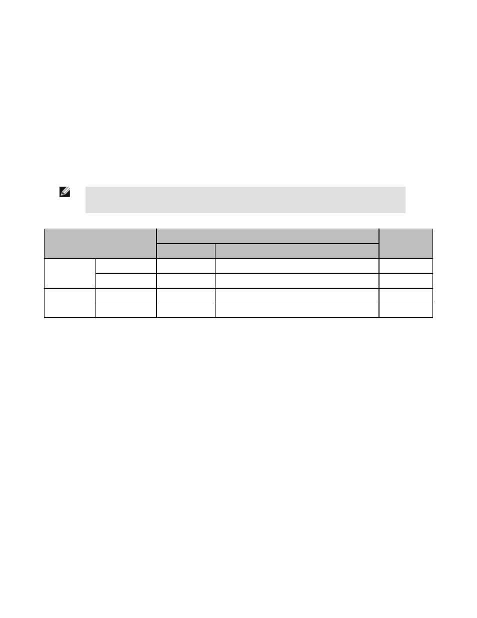
Indicator and Output Behavior
NOTE: "C3" and "C4" models as referenced in the table pertain to a part of the product model number, imme-
diately preceding the QPMA designation.
Sensor Conditions
Job Light
Output Signal
Status
C3 Models
C4 Models
Job input active
Hand/pick absent
ON Green
ON Green
OFF
Hand/pick present
ON Yellow
ON Yellow until job input is removed
ON
No job input
Hand/pick absent
OFF
OFF
OFF
Hand/pick present
ON Red
ON Red for 5 seconds after hand/pick is removed
ON
Specifications
Supply Voltage and Current
12 to 30V dc (10% max. ripple)
Less than 90 mA max. current at 12V dc (exclusive of
load)
Less than 60 mA max. current at 30V dc (exclusive of
load)
Supply Protection and Circuitry
Protected against transient voltages (fast-transient and
over-voltage) and reverse polarity
Output Configuration
1 current sinking (NPN) transistor or 1 current sourcing
(PNP) transistor, depending on model. Retroreflective
models have normally closed (N.C.) output; all other
models have normally open (N.O.) output.
Output Rating
Max. load: 150 mA
ON-state saturation voltage:
PNP models: < 2V at 10 mA dc; < 2.5V at 150 mA dc
NPN models: < 1.5V at 10 mA dc; < 2V at 150 mA dc
OFF-state leakage current: < 10 µA at 30V dc
Job Light Enable
Input impedance: 8K Ohms
Sinking – Input low < 1.0V
Sourcing – Input high > 7V
Construction
Base: polycarbonate
Translucent dome: polycarbonate
Push button: thermoplastic
Lens: polycarbonate or acrylic
Connections
150 mm pigtail with 5-pin Euro-style QD fitting (QPMA);
accessory cordset required for QD models.
Ambient Light Immunity
Up to 5,000 lux
EMI-RFI Immunity
Immune to EMI and RFI noise sources, per IEC
947-5-2.
Environmental Rating
Fully encapsulated; IEC IP67
Integral QD models meet DIN 40050 (IP69K) when us-
ing IP69K-rated cables; pigtail and cable models meet
IP69K when mounted with conduit
EZ-LIGHT® K50 and K80 Specialty — 3-Color
2
www.bannerengineering.com - tel: 763-544-3164
P/N 137551_web
Rev. C