Q45lma analog output card, Response speed settings – Banner U-GAGE Q45U Series—Analog User Manual
Page 3
page
3
Q45LMA Analog Output Card
Banner Engineering Corp.
•
Minneapolis, U.S.A.
www.bannerengineering.com • Tel: 763.544.3164
Explanation of Programmable Output Functions:
Switch 1:
Output Slope Select
On = Direct = Output value (voltage or current) increases with increasing distance
of the target from the sensor
Off* = Inverse = Output value decreases with increasing distance of the target
from the sensor
Switch 2:
Output Mode Select
On = The 4 to 20mA current output (white wire) is enabled
Off* = The 0 to 10V dc voltage output (black wire) is enabled
This switch configures the D/A driver to use either the current output or the voltage
output driver. This output function can only be set with the power to
the sensor turned off.
Switch 3:
Loss of Echo Mode Select
On = Min - Max Mode
Off* = Hold Mode
This switch determines the output response to the loss of echo. The “Hold Mode”
(Switch 3 Off*) maintains the output at the value which was present at the time of
echo loss. The “Min - Max Mode” (Switch 3 On) drives the output to either the
minimum value (0V or 4mA or the maximum value (10V or 20mA) when the echo is
lost. Minimum or maximum value is selected by Switch 4.
Switch 4:
Min - Max Default
On* = Default to maximum output value at loss of echo
Off = Default to minimum output value at loss of echo
Switch 4 selects the output response to loss of echo when “Min - Max Mode” is
selected by Switch 3 (see above).
Response Speed Adjustment
The speed of the output response is set using the single-turn potentiometer (see
Figures 1 and 6). There are six values for response speed, which relate directly to the
number of sensing cycles over which the output value is averaged. The response
value is set by aligning the slot of the potentiometer with one of the marked positions.
The positions and their corresponding settings are identified in Figure 6.
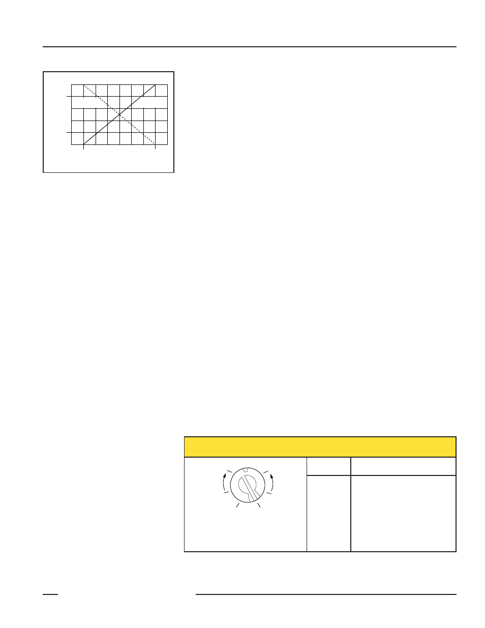
Inverse Slope
Switch 1 Off
Direct Slope
Switch 1 On
Near
Window
Limit
Far
Window
Limit
10V dc
(20mA)
0V dc
(4mA)
Figure 5. Output Slope
Res
Position
Response Speed
1
2
3
4
5
6
40 milliseconds (2 cycles)
80 milliseconds (4 cycles)
160 milliseconds (8 cycles)
320 milliseconds (16 cycles)
640 milliseconds (32 cycles)
1280 milliseconds (64 cycles)
Figure 6. Response adjustment positions and their corresponding response speed values
1
2
3
4
5
6
NOTE: This example shows the potentiometer
set at position number 4. There are no
numbers on the actual product label.
+
–
Response Speed Settings