Q45lma analog output card, Programming the 45lma card – Banner U-GAGE Q45U Series—Analog User Manual
Page 2
Q45LMA Analog Output Card
page
2
Banner Engineering Corp.
•
Minneapolis, U.S.A.
www.bannerengineering.com • Tel: 763.544.3164
Programming the 45LMA Card
Status Indicators:
Status indicator LEDs are visible through the transparent, o-ring sealed Lexan
®
top
cover. Indicator function in the RUN mode is, as follows:
• The green LED is on steadily whenever power is applied to the sensor, and flashes
to indicate a current output fault.
• The red LED lights when an echo is received, and flashes at a rate that is
proportional to echo strength.
• The yellow LED lights whenever the target is within the operating window limits.
The 5-segment moving dot LED indicator displays the relative position of the target
within the programmed sensing window. The #1 LED flashes when the target is
closer than the near limit. The #5 LED flashes when the target is beyond the far limit.
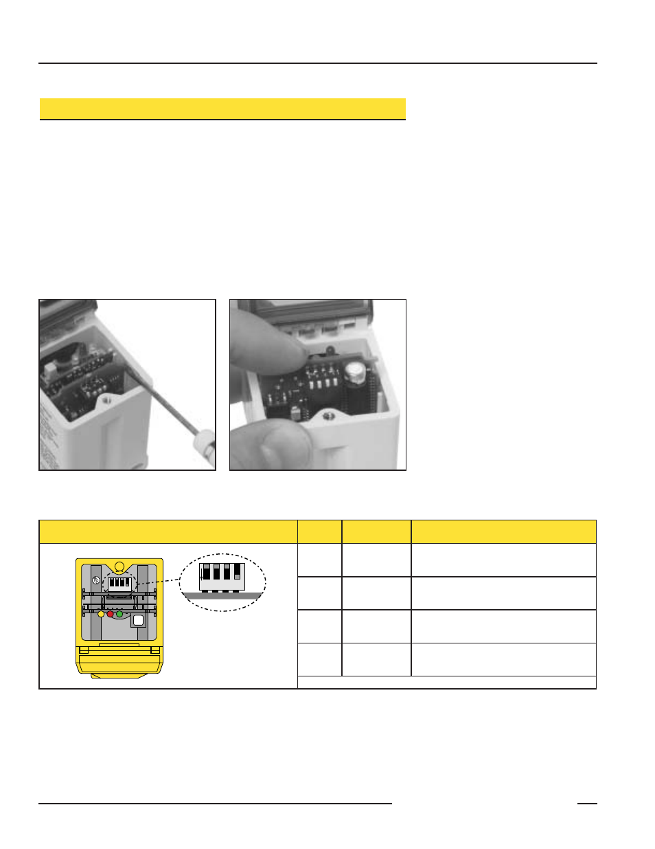
Figure 2. Remove the output card using a
small screwdriver to dislodge it
from its connector.
Figure 3. Slide the 45LMA card into the
sensor and push it firmly into
place.
Switch
Function
Settings
1
Output Slope
On
= Output value increases with distance
Off* = Output value decreases with distance
2
Output Mode
On
= Current output enabled
Off* = Voltage output enabled
3
Loss of Echo
On
= Min - Max Mode
Off* = Hold Mode
4
Min - Max
On* = Default to maximum output value
Off = Default to minimum output value
Figure 4. 45LMA programming switches and their functions
*Indicates factory settings
1
ON
2
3
4
See Table Below for
Programming Information
Output Response Settings:
IMPORTANT: Remove power before making any internal adjustments.
Using the two slots shown in Figure 1, a small flat-blade screwdriver may be used to lift
up and remove the black inner cover to expose the 4-position DIP switch (Figure 2).
Those switches are used to program the functions as indicated in Figure 4.