Dimensions – Banner U-GAGE Q45U Series—Analog User Manual
Page 7
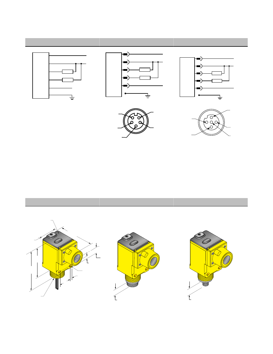
Hookup Diagrams for Q45U Sensors with Analog Outputs
Sensor with Attached Cable
Sensor with 5-pin Mini-style QD
Sensor with 5-pin Euro-style QD
bn
wh
bu
–
bk
ye or gy
15–24V dc
4 to 20mA
0 to 10V
Remote teach
(+5–24V dc)
Load
Load
+
shield
bn
wh
bu
–
bk
ye
4 to 20mA
0 to 10V
Remote teach
(+5–24V dc)
Load
Load
+
15–24V dc
shield
bn
wh
bu
–
bk
gy
4 to 20mA
0 to 10V
Remote teach
(+5–24V dc)
Load
Load
+
15–24V dc
shield
Banner Engineering Corp recommends the
shield wire be connected to earth ground or
dc common.
4
3
1
5
2
1 = brown
2 = white
3 = blue
4 = black
5 = yellow
2
3
4
1
5
1 = brown
2 = white
3 = blue
4 = black
5 = gray
Dimensions
Cabled Models
5-pin Mini-style QD Models
5-pin Euro-style QD Models
79.4 mm
(3.13")
44.5 mm
(1.75")
69.0 mm
(2.72")
87.6 mm
(3.45")
30.0 mm
(1.18")
Internal Thread: (1/2 NPSM)
External Thread: (M30 x 1.5)
ø6.1 mm (.24")
2 m (6.5') Cable
7.1 mm
(0.28")
4.5 mm (#10) Screw
Clearance (2)
50.3 mm
(1.98")
6.4 mm (0.25")
Transducer
Centerline
Transparent Cover (Gasketed)
View: Sensing Status
Output Load Status
Power
Open to Access:
Push Button for
Programming of Sensing
Window Limits
Hex Nut Supplied
14 mm (0.6")
15 mm (0.6")
Q45U Ultrasonic Sensors with Analog Outputs (Long Range)
P/N 48456 Rev. E
www.bannerengineering.com - tel: 763-544-3164
7