Response speed adjustments – Banner U-GAGE Q45U Series—Analog User Manual
Page 3
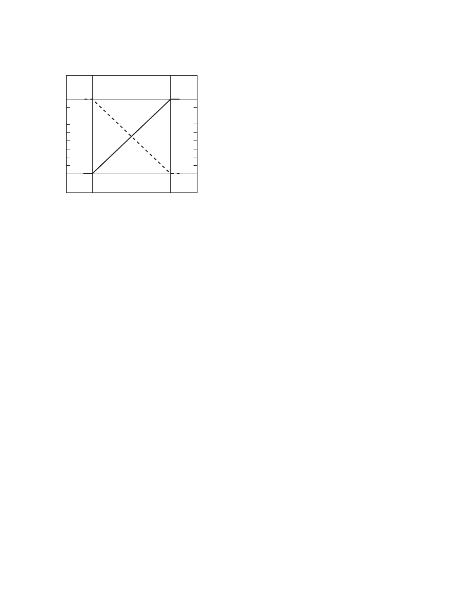
DIP Switch 1: Output Slope Select
0
Near
Window
Far
Window
10
Target Position
Analog Output
(V dc)
Positive
Slope
Voltage/Current-Sourcing Models
4
20
Analog Output
(mA)
Figure 3. Output as a function of target position
On = Direct = Output value (voltage or current) increases with in-
creasing distance of the target from the sensor
Off* = Inverse = Output value decreases with increasing distance
of the target from the sensor
DIP Switch 2: Output Mode Select
On = The 4 to 20 mA current output (white wire) is enabled
Off* = The 0 to 10V dc voltage output (black wire) is enabled
This switch configures the D/A driver to use either the current output or the voltage output driver. This output function can only be set with
the power to the sensor turned off.
DIP Switch 3: Loss of Echo Mode Select
On = Min - Max Mode
Off* = Hold Mode
This switch determines the output response to the loss of echo. The “Hold Mode” (Switch 3 Off*) maintains the output at the value
present at the time of echo loss. The “Min - Max Mode” (Switch 3 On) drives the output to either the minimum value (0V or 4 mA or the
maximum value (10V or 20 mA) when the echo is lost. Minimum or maximum value is selected by DIP switch 4.
DIP Switch 4: Min-Max Default
On* = Default to maximum output value at loss of echo
Off = Default to minimum output value at loss of echo
Switch 4 selects the output response to loss of echo when “Min - Max Mode” is selected by DIP switch 3.
Response Speed Adjustments
The speed of the output response is set using the single-turn potentiometer. There are six values for response speed, which relate direct-
ly to the number of sensing cycles over which the output value is averaged. The response value is set by aligning the slot of the potenti-
ometer with one of the marked positions.
Q45U Ultrasonic Sensors with Analog Outputs (Long Range)
P/N 48456 Rev. E
www.bannerengineering.com - tel: 763-544-3164
3