Adjustment information, Sonic omni-beam analog outputs, Power blocks with analog output – Banner U-GAGE Sonic OMNI-BEAM Ultrasonic Sensors User Manual
Page 5: Sensing window adjustment, Negative slope, Positive slope
Adjustment Information
5
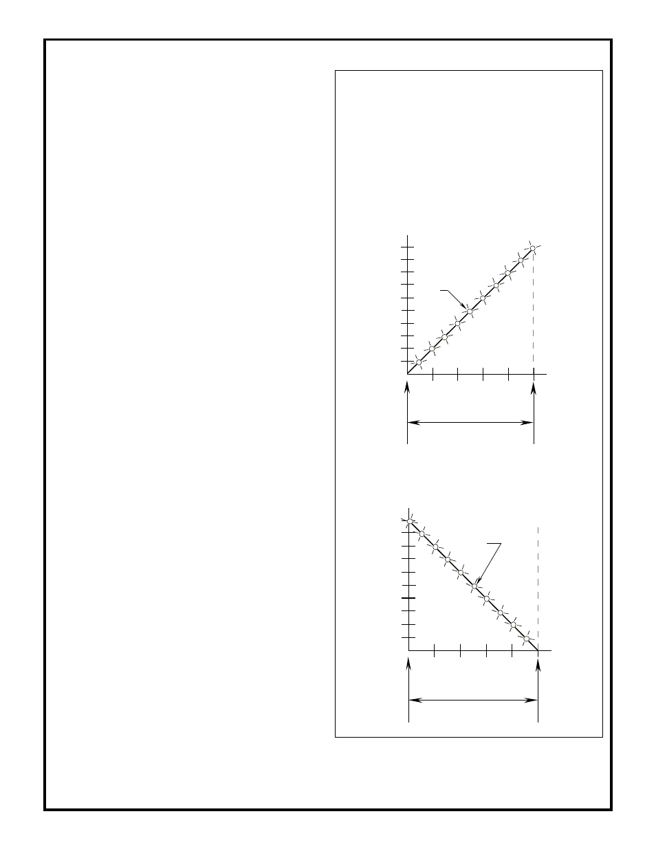
The graphs below show the relationship between the target object
position within the sensing window, the number of LED array
indicators "on", and the analog dc voltage output for sonic
OMNI-BEAM sensor block module model OSBUSR used with
one of the following analog power block modules: OPBA3,
OPBA3QD; OPBB3, OPBB3QD; OPBT3, OPBT3QD. Graphs
for both positive slope and negative slope output are shown.
Power Blocks with ANALOG Output
The programming DIP switches inside the OSBUSR sensor block have
no effect when using analog power blocks. The only adjustments are to
the NEAR and WIDTH potentiometers. Note: The status of the LOAD
indicator LED should be disregarded when a sensor with an analog
power block is being adjusted.
Sensing Window Adjustment
A dc voltmeter is used to locate and to "size" the sensing window. The
NEAR and FAR limit adjustments on top of the sensor head (see photo
on page 4) are 15-turn potentiometers, clutched at both ends of travel.
They are adjusted using a small, flat-blade screwdriver. Clockwise
rotation of either limit adjustment moves that window limit farther
away from the sensor. Counterclockwise rotation moves that limit
closer to the sensor.
Refer to the hookup drawings for ANALOG output power blocks on
page 3. If the positively-sloped power block output (black wire) is used,
the analog value of the output increases from 0 to +10 volts dc as the
sensor-to-target distance increases. If the negatively-sloped power
block output (white wire) is used, the analog value of the output
decreases from +10 to 0 volts as the sensor-to-target distance increases.
The window width may be set at from 3 inches to 22 inches. This
sensing window may be placed anywhere within the 4 to 26 inch sensing
range of the OSBUSR sensor block. NOTE: The NEAR limit may be
referenced as close as zero inches (i.e. zero inches equals zero volts or
+10 volts output); however, sensing is not reliable within the first 4
inches from the transducer face.
The factory settings are:
Near limit (NEAR control) = 0 inches
Far limit (WIDTH control) = 26 inches
With these settings, the voltage at the minimum sensing range (4 inches)
will be approximately 1.6V dc (positive slope selected) or 9.4V dc
(negative slope selected).
Window adjustment procedure:
1) Remove the transparent plastic top cover of the sensor head for
access to the NEAR and WIDTH adjustments. Connect a dc voltmeter
across either the black and yellow wires or the white and yellow wires
of the cable (depending upon the output to be used) with or without the
load connected. Connect the brown and blue power supply wires from
the cable to a suitable power source and apply power.
2) Position the target material at the desired near limit of the sensing
window. Rotate the NEAR limit control to the point where the output
voltage just equals 0.0 V dc (black and yellow output wires in use,
positive slope) or 10.0V dc (white and yellow output wires used,
negative slope). For positive slope adjustment, rotate the control
clockwise to decrease the voltage; rotate counterclockwise to increase
the voltage. For negative slope adjustment, rotate counterclockwise to
decrease and clockwise to increase.
3) Move the target material to the desired far limit of the sensing
window and rotate the WIDTH control to find the point at which the
output voltage just equals 10.0 V dc (positive slope) or 0.0V dc
(negative slope). For positive slope adjustment, rotate the control
clockwise to decrease the voltage; rotate counterclockwise to increase
the voltage. For negative slope adjustment, rotate counterclockwise to
decrease and clockwise to increase.
4) Reposition the target material at the near limit and readjust the
NEAR limit control, if necessary, to re-establish the correct dc output
(repeat step #2).
5) If any adjustment was necessary in step #4, recheck the far limit and
readjust the WIDTH control (repeat step #3), if necessary.
Sonic OMNI-BEAM Analog Outputs
0
2
4
6
8
10
1
3
5
7
9
Near Limit
Far Limit
Sensing Window Width
Output (V dc)
10
9
8
7
6
5
2
1
Position Indicator
LEDs
3
4
Negative slope
Negative slope:
output voltage decreases with target distance
Near Limit
Far Limit
Sensing Window Width
Output (V dc)
10
9
8
7
6
5
4
3
2
1
Position Indicator
LEDs
0
2
4
6
8
10
1
3
5
7
9
Positive slope
Positive slope:
output voltage increases with target distance
6) The moving-dot LED display will confirm the window dimen-
sions by indicating the relative position of the target within the
established window, in 10% increments.