R58 expert, Registration mark sensors, Dynamic teach – Banner R58 Registration Mark Sensors User Manual
Page 5: Maximum feed rate, Dynamic teach and manual adjust, Teach sensing conditions, Return to run mode
P/N 122928 rev. C
5
Banner Engineering Corp. • Minneapolis, MN U.S.A
www.bannerengineering.com • Tel: 763.544.3164
R58
Expert
™
Registration Mark Sensors
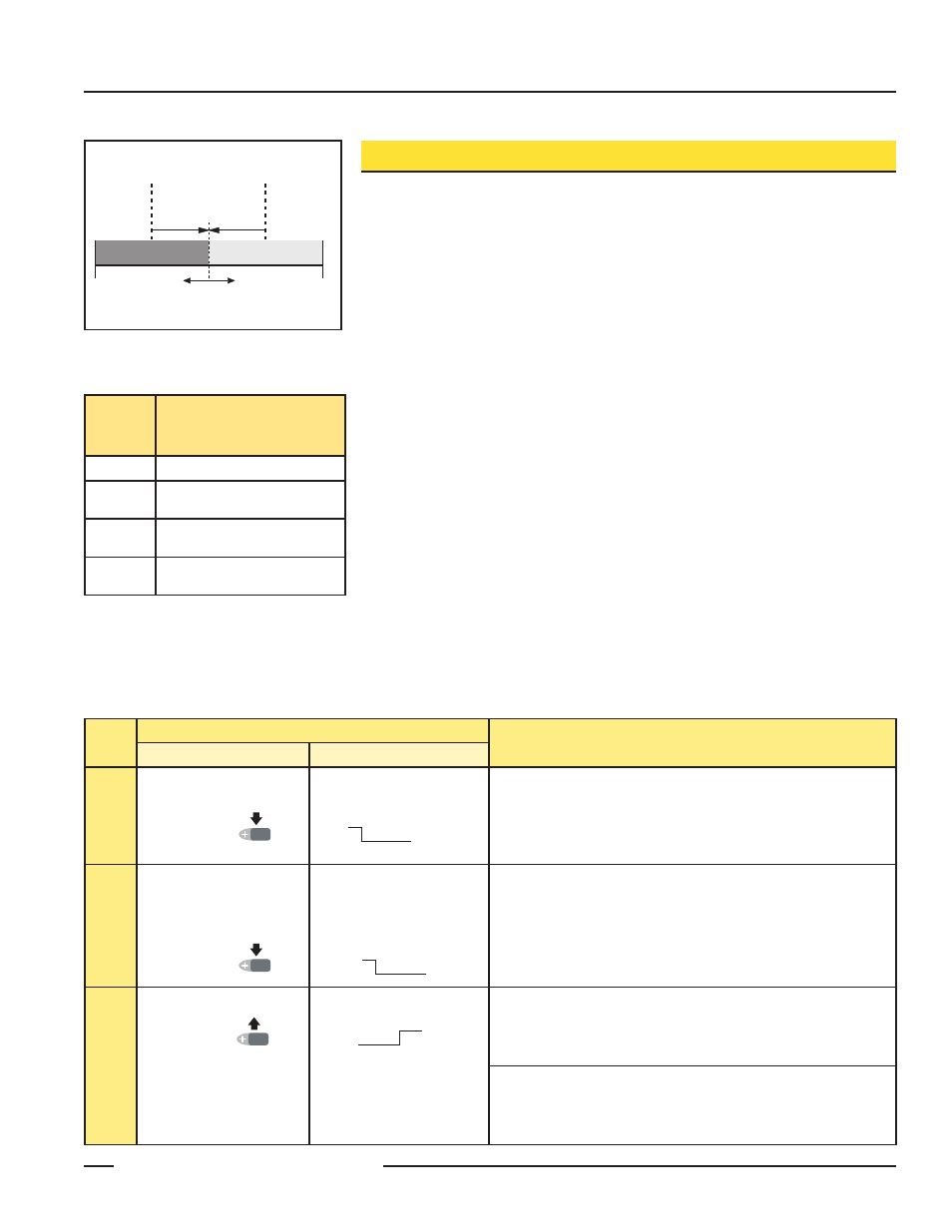
Dynamic TEACH
Dynamic TEACH is used to configure sensitivity during actual sensing conditions, when
looking for a mark against its background condition. The R58E takes multiple samples of the
registration mark against its background material and automatically positions the threshold at the
optimum level. See Figure 2. The registration mark must be presented at least two times during
Dynamic TEACH.
When Dynamic TEACH is used, the Output ON state will be the shorter duration (smaller)
event sensed, and LO/DO will be set accordingly. To change the output state, change to either
LO or DO in SETUP mode, or pulse the remote line three times (see page 8).
Maximum Feed Rate
In order to optimize performance and ensure that all LED color and gain combinations
are evaluated during Dynamic TEACH, the registration mark must encompass the 1.2 mm
dimension of the 1.2 mm x 3.8 mm sensing image for at least 0.002 seconds. Therefore, the
maximum feed rate can be determined with the following formula:
Maximum Feed Rate in mm/sec. = (registration mark width in mm – 1.2) / 0.002
Example with a 5 mm registration mark:
Maximum Feed Rate = (5 mm – 1.2) / 0.002 = 1900 mm/sec.
NOTE: Registration marks narrower than the 1.2 mm sensing image width can be detected at
feed rates less than 600 mm/sec, but the contrast will be reduced, due to averaging of
the background and the registration mark.
Dynamic TEACH and Manual Adjust
Sensitivity may be adjusted at any time when the sensor is in RUN mode by clicking the “+”
and “-” buttons. Each click translates to 1/2 segment on the bargraph display. For best sensing
reliability, the light and dark conditions should register equally distant from the switchpoint on
the bargraph display.
Procedure
Result
Push Button
Remote Line
Access
TEACH
Mode
• Press and hold the
Dynamic push button
for > 2 seconds.
• Hold the remote line low
for > 2 seconds.
LO and DO: Alternately flash Green
Output: OFF
Bargraph display: Goes OFF
Teach
Sensing
Conditions
• Continue to hold Dynamic
push button.
• Present sensing conditions
(present registration mark
at least twice).
• Continue to hold the remote
line low.
• Present sensing conditions
(present registration mark
at least twice).
LO and DO: Alternately flash Green
Output: OFF
Bargraph display: Remains OFF
Return
to
RUN
Mode
• Release the Dynamic
push button.
• Release remote line/switch.
Teach Accepted
• Bargraph display flashes one segment for three seconds to indicate
relative contrast (see contrast table above).
• Sensor enters RUN mode.
Teach Unacceptable
• Pairs of bargraph display segments flash in unison for three seconds to
warn of unacceptably low contrast.
• Sensor returns to RUN mode without changing settings.
T
T T T
T
T
0.8 seconds
> 2 seconds
T
T
T
T
T
T
T
T
T
T
T
T
T
T
T
T
T
T
T
T
T
T
T
T
T
T
T
T
T
T
T
T
T
T
T
T
T
T
T
T
T
T
T
T
T
T
T
T
T
T
T
T
T
T
T T T
T
T
0.8 seconds
> 2 seconds
T
T
T
T
T
T
T
T
T
T
T
T
T
T
T
T
T
T
T
T
T
T
T
T
T
T
T
T
T
T
T
T
T
T
T
T
T
T
T
T
T
T
T
T
T
T
T
T
T
T
T
T
T
T
T T T
T
T
0.8 seconds
> 2 seconds
T
T
T
T
T
T
T
T
T
T
T
T
T
T
T
T
T
T
T
T
T
T
T
T
T
T
T
T
T
T
T
T
T
T
T
T
T
T
T
T
T
T
T
T
T
T
T
T
T
T
T
T
T
Bargraph
Display
Segment*
Relative Contrast /
Recommendation
6 to 8
Excellent: Very stable operation.
4 to 5
Good: Minor sensing variables
will not affect sensing reliability.
2 to 3
Low: Minor sensing variables
may affect sensing reliability.
1
Poor: Consider an alternate
sensing scheme.
*Following TEACH
NOTE: High contrast relates directly to sensing
reliability; high-contrast sensing applications are
most tolerant of sensing variables (e.g., web flutter or
variations in registration mark color and print density).
Sensor positions
threshold midway
between taught conditions
Sensor positions
threshold midway
between taught conditions
Darkest
(no signal)
Most Light
(saturated
signal)
Single
taught
point
Sensing window size
adjusted by
Manual Adjust
Output OFF
Output OFF
Output OFF
Output ON
Output ON
Condition of
Longer Duration
Condition of
Shorter Duration
Position
adjusted by
Manual Adjust
Output OFF
Output ON
2nd Taught
Condition
1st Taught
Condition
Position
adjusted by
Manual Adjust
Figure 3. Dynamic TEACH (Light or Dark
Operate, depending on the sensing
condition shown)