Hookup using one dual-channel barrier – Banner SMI30 Series—Intrinsically Safe User Manual
Page 4
3
4
5
6
7
8
2
1
11
10
9
105 to 130V ac
In
I.S.
+
+
–
–
I.S. Barrier
Out
CI3RC2
210 to 250V ac
AC
Supply
Relay Output
5 Amp Contacts
Input:
10mA (OFF State)
20mA (ON State)
Aux.
Blue
Brown
3
2
1
Input
Common
Opto-Coupler
Output: 20mA max.
Earth Ground
(less than 1)
Non-Hazardous Area
Hazardous Area
SMI Series
Emitter
G
Busbar
In
I.S.
+
+
–
–
I.S. Barrier
Out
Bottom View of Cable
Connector on Sensor
(colors shown are for mating
cable model SMICC-3xx)
Blue
Brown
3
2
1
SMI Series
Receiver
Black
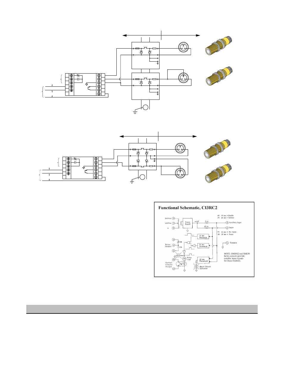
Hookup Using One Dual-Channel Barrier
3
4
5
6
7
8
2
1
11
10
9
105 to 130V ac
In +
+
+
+
–
–
Dual Barrier
I.S.
In
Out
Out
CI3RC2
210 to 250V ac
AC
Supply
Relay Output
5 Amp Contacts
Bottom View of Cable
Connector on Sensor
(colors shown are for mating
cable model SMICC-3xx)
Input:
10mA (OFF State)
20mA (ON State)
Aux.
Blue
Blue
Brown
Brown
Black
3
2
1
1
3
2
Input
Common
Opto-Coupler
Output: 20mA max.
Earth Ground
(less than 1)
Non-Hazardous Area
Hazardous Area
SMI Series
Emitter
SMI Series
Receiver
G
Busbar
Both sensors of the opposed mode pair are wired to model CI3RC2 us-
ing the two-wire hookup, which requires the use of two single channel
or one dual channel intrinsic safety barrier(s). In this mode, the SMI30
receiver sinks less than or equal to 10 milliamps in the "OFF" state and
greater than or equal to 20 milliamps in the "ON" state. The CI3RC2
senses this current change and switches internal relays that are easily
wired to most loads and/or additional control circuitry.
Model CI3RC2 is powered by either 105 to 130 or 210 to 250V ac. The
CI3RC2 supplies power to operate both the emitter and receiver.
Inputs are protected against short circuits. Built-in circuit diagnostics in-
dicate an overload of either input by pulsing an LED status light.
The CI3RC2 module has two isolated output switches. There is a 5
amp rated SPDT electromechanical relay, and a solid-state transistor
switch which may be used for logic-level interfaces.
For more information, refer to the datasheet packed with the CI3RC2.
CI3RC2 Specifications
General
Output Configuration
Supply Voltage
105 to 130 or 210 to 250V ac, 50/60 Hz (8VA)
Indicator LEDs
SPDT Electromechanical Relay
Contact rating: 250V ac max., 24V dc max., 5 amps
max. (resistive load), 1/10 HP at 240V ac. Install transi-
SMI30 Series Intrinsically Safe Sensors
4
www.bannerengineering.com - tel: 763-544-3164
P/N 035331 Rev. E