U-gage, M25u series sensor, Specifications – Banner U-GAGE M25U Ultrasonic Sensors User Manual
Page 3: Hookups
P/N 137794 rev. D
3
Banner Engineering Corp. • Minneapolis, MN U.S.A
www.bannerengineering.com • Tel: 763.544.3164
U-GAGE
®
M25U Series Sensor
Specifications
Sensing Range
Normal Speed: 500 mm (19.7")
High Speed: 250 mm (9.8")
140KHz
Supply Voltage and Current
Emitter: 10 to 30V dc (10% max. ripple) at less than 85 mA
Receiver: 10 to 30V dc (10% max. ripple) at less than 38 mA (exclusive of load)
Supply Protection Circuitry
Protected against reverse polarity and transient voltages
Receiver Output Configuration
Bipolar (1 NPN & 1 PNP) solid-state output;
Normally Closed (output is activated when an object blocks the sensing beam)
Output Rating
100 mA (each output) with short circuit protection; see Note 1
OFF-state leakage current: NPN: < 200 µA sinking PNP: < 10 µA sourcing
ON-state saturation voltage: NPN: < 1.6V @ 100 mA PNP: < 3.0V @ 100 mA
Output Protection Circuitry
Protected against short circuit conditions
Output Response Time
Normal Speed: 4.0 milliseconds
High Speed: 3.0 milliseconds
Repeatability
1 millisecond
Delay at Power-up
< 250 milliseconds
Delay for Switching Between
Normal and High Speed
20 milliseconds
Indicators
Green Power LED: indicates Power ON
Amber Output LED: indicates output activated
Construction
Housing: 316 Stainless Steel
LED window: Polysulphone
Connections
Emitter: 4-pin Euro-Style QD
Receiver: 5-pin Euro-Style QD
Environmental Rating
Leakproof design, rated IEC IP67 (NEMA 6), IP69K
Operating Conditions
Temperature: -20° to +70°C (-4° to +158° F)
Max. Relative Humidity: 95% at 50°C non-condensing
Vibration and
Mechanical Shock
All models meet Mil. Std. 202F requirements method 201A (vibration: 10 to 60 Hz max. amplitude 0.06", max.
acceleration 10G). Also meets IEC 947-5-2; 30G 11 ms duration.
Certifications
Notes
1. NPN < 200 µA for load impedance > 3 KΩ; for load current of 100 mA, leakage < 1% of load current
2. When mounting the M25U, care should be taken to acoustically isolate the emitter and receiver to eliminate
sound energy coupling between the sensor pair. This is best accomplished with elastomeric materials between
the sensor and rigid mounting brackets.
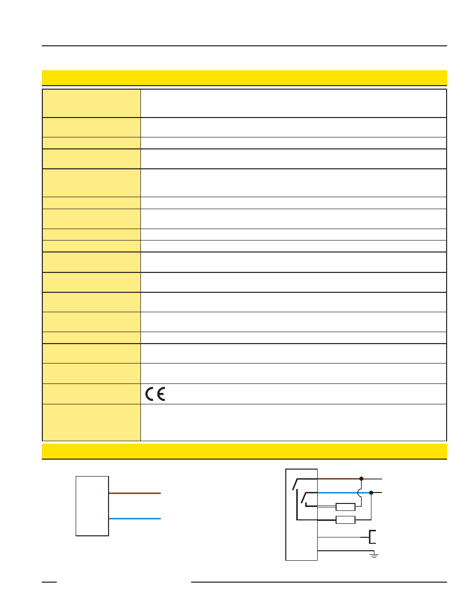
Hookups
Emitter
Receiver
* NOTE: Connection of dc power is without regard to polarity.
1
3
+ 10-30V dc
Shield*
10-30V dc
–
+
1
3
2
4
5
Load
Load
* It is recommended that the shield wire be connected to
either earth ground or DC common.
Normal Speed
(5-30V dc)
High Speed
(0-2V dc)
5-Pin Euro
1 = Brown
2 = White
3 = Blue
4 = Black
5 = Gray
Key
1 = Brown
2 = White
3 = Blue
4 = Black
5 = Gray