Vs2 series – opposed mode, Vs2 series opposed-mode sensor specifications, Vs2 series sensor hookups – Banner VS2 Series User Manual
Page 2
VS2 Series – Opposed Mode
page
2
Banner Engineering Corp.
•
Minneapolis, MN U.S.A.
www.bannerengineering.com • Tel: 763.544.3164
VS2 Series Opposed-Mode Sensor Specifications
Supply Voltage and Current
Supply Protection Circuitry
Protected against reverse polarity and transient voltages
Output Configuration
SPST solid-state switch
Choose NPN (current sinking) or PNP (current sourcing) models
Choose light operate (N.O.) or dark operate (N.C.) models
Output Rating
50 mA maximum
Off-state leakage current: < 1 microamp at 24V dc
On-state saturation voltage: < 0.25V at 10 mA dc; < 0.5V at 50 mA dc
Output Protection Circuitry
Protected against false pulse on power-up and continuous overload or short circuit of outputs
Overload trip point ≥ 100 mA
Output Response Time
1 millisecond ON and 0.5 milliseconds OFF
(NOTE: 100 millisecond delay on power-up: output is non-conducting during this time)
Indicators
Two LEDs: Green and Yellow
Green ON steady
= power to sensor is ON
Green flashing
= output overload
Yellow ON steady
= light is sensed
Yellow flashing
= marginal excess gain (1-1.5x) in light condition
Repeatability
100 microseconds
Construction
Black ABS housing with clear MABS lens
Environmental Rating
IP67; NEMA 6
Connections
2 m (6.5') attached cable: three #28 ga stranded conductors with PE insulation; PVC outer cable jacket;
or 3-pin Pico-style pigtail quick-disconnect fitting. QD cables are ordered separately.
Operating Conditions
Temperature: -20° to +55°C (-4° to +131°F)
Maximum Relative Humidity: 80% at 50°C (non-condensing)
Vibration and
Mechanical Shock
Vibration: All models meet IEC 60068-2-6, IEC 60947-5-2, UL491 Section 40, MIL-STD-202F Method 201A;
10 to 60 Hz, 0.5 mm peak to peak
Shock: All models meet IEC 60068-2-27, IEC 60947-5-2; 30g peak acceleration, 11 millisecond pulse
duration, half-sine wave pulse shape
10 to 30V dc (10% maximum ripple)
Emitter: 25 mA (visible beam); 30 mA (infrared beam)
Receiver: 25 mA (exclusive of load)
Certifications
Application Notes
M2 stainless steel mounting hardware included. Optional mounting brackets are available (page 4).
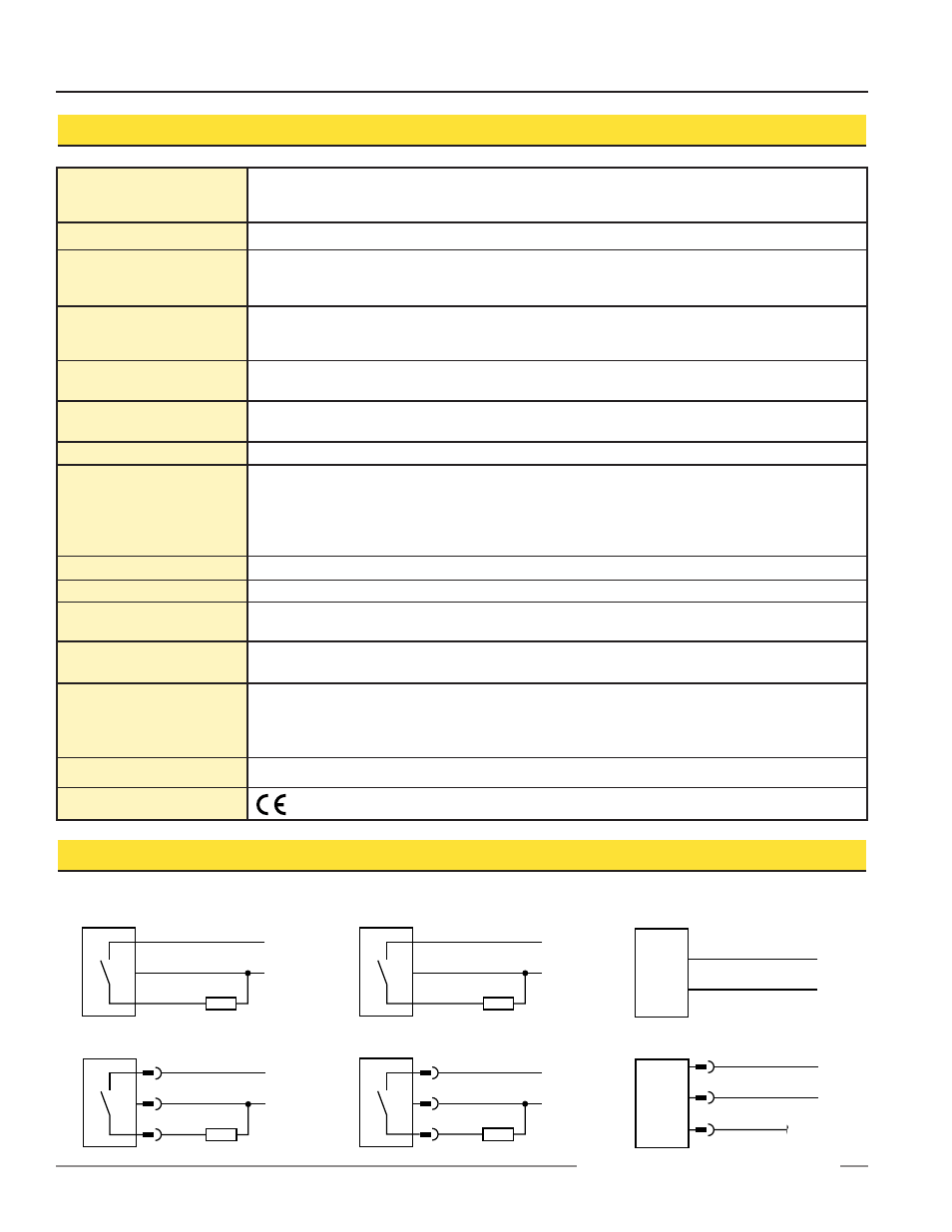
VS2 Series Sensor Hookups
10-30V dc
–
+
bu
bn
bk
Load
10-30V dc
–
+
bn
bu
bk
Load
10-30V dc
+
–
bu
bn
10-30V dc
–
+
bu
bn
bk
Load
10-30V dc
–
+
bn
bu
bk
Load
10-30V dc
+
–
bu
bn
bk
Sensors with NPN Outputs
Cabled hookup
Quick-Disconnect hookup
Quick-Disconnect hookup
Quick-Disconnect hookup
Emitters
Cabled hookup
Sensors with PNP Outputs
Cabled hookup