Wiring connections, Dimensions – Banner VALU-BEAM SMI912 Series—Intrinsically Safe User Manual
Page 7
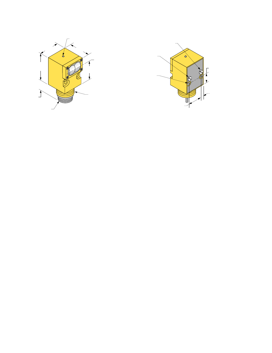
Dimensions
26.7 mm
(1.05")
Mini-style
Quick-disconnect
M30 x 1.5 Thread
Hex Nut Supplied
36.6 mm
(1.44")
35.6 mm
(1.40")
LED Indicator
Lens Centerline
50.8 mm
(2.00")
39.1 mm
(1.54")
Light/Dark Operate Select
(L.O. = CW, D.O. = CCW)
Sensitivity Control
(Turn CW to Increase)
25.4 mm
(1.00")
4.5 mm
(#10) Screw Clearance (2)
17.8 mm
(0.70")
5.6 mm
(0.22")
Control potentiometers are behind cover screws;
remove screws to access controls
Wiring Connections
SMI912 Series sensors are certified intrinsically safe ONLY when used with certified energy-limiting intrinsically safe barriers. Banner
does not manufacture such barriers; however, our applications engineers can refer you to suppliers of certified barriers that will interface
with Banner sensors. SMI912 Series sensors may be wired using Banner Current Amplifier Control Module CI3RC2 (see page 9). Note
from the hookup diagrams (page 8) that the installation may be made with either a single barrier (2-wire hookup) or with a double barrier
(3-wire hookup). Emitter-only units (SMI91EQD, ESRQD, and EFQD) use the 2-wire hookup; all other models use either 2- or 3-wire
hookup.
In the 2-wire configuration, the sensor will act as a current sink, drawing less than 10 mA in the OFF state and more than 20 mA in the
ON state. The user must provide a current sensing device (“current sensor” in the diagram) to convert the current to a logic level. In the 3-
wire configuration, the output may be used directly to control loads of less than 15 mA.
In selecting the barrier, it is important to consider the barrier's resistance. The sensor must have at least 10 volts across the brown and
blue power leads for proper operation, and the barrier will cause a voltage drop due to its resistance. The formula that determines how
much resistance is allowed is:
R = 40 (supply voltage – 10 volts)
If the supply voltage is 24V dc, then the maximum resistance is 560 ohms. If the supply voltage is 18V dc, then the maximum resistance
is 320 ohms. This includes the resistance of any current sensing device used (in the 2-wire configuration), so the barrier resistance must
be further reduced by the current sensor resistance.
Note that, in the 3-wire hookup, the positive load barrier is in series with the load. This will result in an apparent saturation voltage of the
output that is higher than the sensor output by the amount of I × R (current times resistance) drop through the barrier.
A “positive input” barrier is required for both supply and for load. The sensor’s blue (negative supply) lead is normally connected to the
ground terminal of the barrier.
The user is responsible for proper installation and maintenance of this equipment, and must conform with the certification requirements
relating to barriers and to maximum allowable capacitance and inductance of the field wiring. If in doubt about these requirements, our
applications engineers can refer you to the appropriate authority.
VALU-BEAM SMI912 Series
P/N 03396 Rev. K
www.bannerengineering.com - tel: 763-544-3164
7