Banner VALU-BEAM SMI912 Series—Intrinsically Safe User Manual
Page 10
Current Trip-Point Module
Model
Description
Maximum switching speed: 20 operations/second.
Mechanical life: 20,000,000 operations
Output Configuration (Solid-state dc relay)
SPST optically-coupled transistor; 30V dc maximum, 20 mA maximum.
Emitter Power
+24V dc at 25 mA maximum available at module pin #3
Inputs
Trip point for output "OFF": ≤ 10 mA
Trip point for output "ON": ≥ 20 mA
Trip point range for input overload indication: 30 mA ≤ I ≤ 80 mA
Indicators
Status Indicators for OUTPUT “ON” and INPUT overload/short
Construction
Housing: rugged polyphenylene oxide (PPO®) 1.6" x 2.3" x 4"
Standard round-pin 11-pole base. Use RS-11 socket or equivalent.
Operating Conditions
Temperature: 0 to +50 °C (+32 to +122 °F)
Intrinsic Safety Barriers
Model (Barrier On-
ly)
Barrier Description
Kit Model
Kit Description
CIB-1
Single-channel intrinsically safe barrier
CI2BK-1
Includes CI3RC2 current amplifier, one RS-11
socket, one DIN-rail mount, one single-channel
intrinsically safe barrier
CI2B-1
Dual-channel intrinsically safe barrier (typi-
cally used in opposed-mode applications)
CI2BK-2
Includes CI3RC2 current amplifier, one RS-11
socket, one DIN-rail mount, one dual-channel in-
trinsically safe barrier
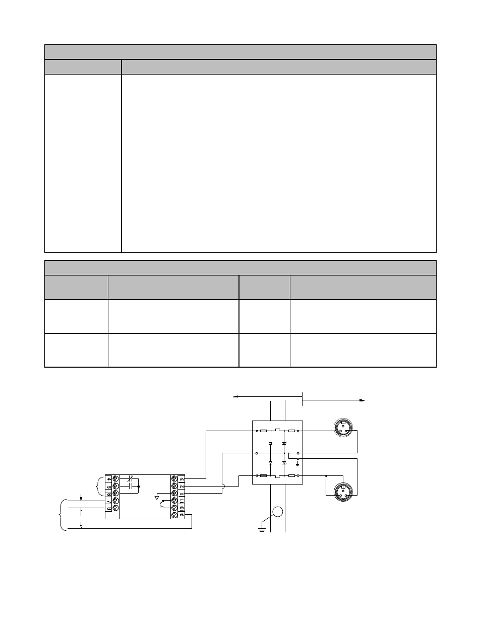
Wiring Connections - SMI912 Series Opposed Mode Emitters and Receivers
4
1
3
Relay outputs
5 amp contacts
105 to 130V ac
210 to 250V ac
AC
supply
CI3RC2
Input:
≤ 10 mA (OFF state)
≥ 20 mA (ON state)
Aux.
Input
Common
OPTO-Coupler
Output: 20 mA max.
Earth ground
(less than 1 ohm)
G
Busbar
Safe Area
Hazardous Area
IN
IN
OUT
OUT
Brown
Black
Brown
Dual Barrier
I.S.
+
+
−
−
+
+
Bottom view of cordset connector
on sensor (colors shown are for
mating cordset model SMICC-312)
SMI Series
Receiver
SMI Series
Emitter
Blue
Blue
4
3
1
Wiring Connections - All Other SMI912 Series Sensors
VALU-BEAM SMI912 Series
10
www.bannerengineering.com - tel: 763-544-3164
P/N 03396 Rev. K