Ql55 series luminescence sensor, Sensor setup output off-delay, Setting npn / pnp output – Banner QL55 Series User Manual
Page 4
QL55 Series Luminescence Sensor
4
P/N 112153 rev. C
Banner Engineering Corp.
•
Minneapolis, MN U.S.A.
www.bannerengineering.com • Tel: 763.544.3164
Sensor
Output
OFF-Delay (20 ms)
Output Ends
Output
Starts
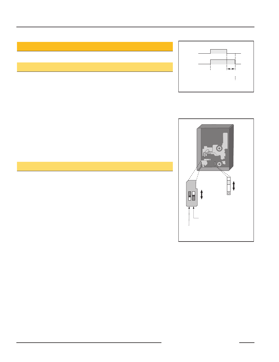
Figure 4. Output OFF-delay: Output
continues for 20 ms after sensing
stops
Sensor Setup
Output OFF-Delay
Setting an output OFF-delay extends the duration of the QL55 sensor’s ON output by
20 ms. See Figure 4. The sensor default is for no OFF-delay.
NOTE: Take precautions against potential static discharge.
To activate the output OFF-delay option:
1. Remove power from sensor.
2. Remove the four cover screws and the sensor side cover.
3. Slide DIP switch 2 (shown in Figure 5) to the ON position.
NOTE: Leave DIP switch 1 in its factory-set position.
4. Change NPN/PNP output selection, if applicable.
5. Replace the sensor side cover and screws.
Setting NPN / PNP Output
The QL55 has a selector switch for setting the output to NPN (current sinking) or PNP
(current sourcing). The sensor is pre-set with the output set to NPN. If the sensor will
be operating with an NPN output (and no output OFF-delay), the sensor housing does
not need to be opened.
NOTE: Take precautions against potential static discharge.
To set NPN or PNP output:
1. Remove power from sensor.
2. Access the red sliding NPN/PNP selector switch by removing the four cover screws
and the sensor side cover. The switch is located deep within the sensor housing;
do not confuse it with the bank of two DIP switches. The NPN/PNP selector switch
is visible below the circuit board, next to the exposed mounting screw location (see
Figure 5).
3. Carefully use a small screwdriver (preferably non-metallic) to select the NPN or
PNP switch position.
4. Replace the sensor side cover and screws before installing the sensor.
NOTE: If a cover screw is lost, contact the Banner applications group for a free
replacement (see back page for addresses).
ON
1 2
OFF-delay
Active
OFF-delay
Inactive
(default)
NPN (default)
PNP
NPN/PNP Selector
(recessed
below top board)
ON
1 2
DIP Switch 2:
Output OFF-Delay Selector
DIP Switch 1:
For factory use only;
leave in OFF position
Figure 5. Selector switches: Output OFF-
Delay and NPN/PNP output select