Wiring diagrams, Accessories – Banner S12 Series User Manual
Page 3
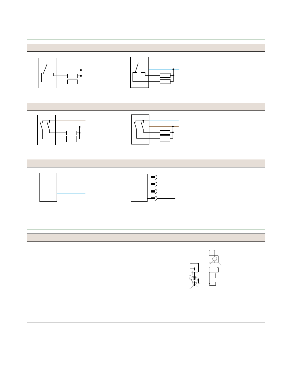
Wiring Diagrams
Receivers with NPN Outputs (Standard)
Receivers with PNP Outputs (Standard)
Key
3
1
−
+
4
2
Load
Load
Load
Load
10–30 V dc
1
3
−
+
4
2
Load
Load
10–30 V dc
1 - Brown
2 - White
3 - Blue
4 - Black
Receivers with NPN Outputs (Alarm)
Receivers with PNP Outputs (Alarm)
Key
10–30 V dc
3
1
−
+
4
2
Alarm
Load
10–30 V dc
1
3
−
+
4
2
Alarm
Load
1 - Brown
2 - White
3 - Blue
4 - Black
Emitters with Attached Cable
Emitters with Quick Disconnect
Key
+
−
10–30 V dc
1
3
1
3
+
−
10–30 V dc
4
2
not used
not used
1 - Brown
2 - White
3 - Blue
4 - Black
Accessories
Brackets
SMB12MM
•
12-gauge, stainless steel, right-angle mounting bracket for
barrel-style sensors with 12 mm threads
•
Curved mounting slot allows the bracket ±10° of lateral
movement
•
Mounting holes accommodate #8 hardware
R 5.1 mm
(0.20")
20
10
ø 4.6 mm
(0.18")
R 3.1 mm
(0.12")
R 24.1 mm
(0.95")
Slot 4.6 mm
(0.18")
12.7 mm
(0.50")
ø 12.3 mm
(0.49")
25.4 mm
(1.00")
42.9 mm
(1.69")
38.1 mm
(1.50")
12.3 mm
(0.49")
Hole center spacing: A to B = 26.0
Hole size: A = ø 4.6, B = 12.8 x 4.6, C= ø 12.3
Aperture Kits. SP12 sensors may be fitted with apertures that narrow or shape the effective beam of the sensor and
protect the sensor’s lens. These apertures are rectangular or circular thread-on water-tight parts. Use of apertures with
SP12 high-gain sensors makes it possible to create very narrow, concentrated sensing beams for precision sensing
applications.
EZ-BEAM S12 Series Opposed-Mode Sensor Pairs
P/N 34501 Rev. B
www.bannerengineering.com - tel: 763-544-3164
3