Specifications, Dimensions – Banner S12 Series User Manual
Page 2
Specifications
Supply Voltage and Current
10 to 30 V dc (10% maximum ripple)
Supply current (exclusive of load current): Opposed Mode Emitters: 25
mA; Opposed Mode Receivers: 20 mA
Supply Protection Circuitry
Protected against reverse polarity and transient voltages
Output Configuration
SPDT (complementary) solid-state dc switch; choose NPN (current
sinking) or PNP (current sourcing) models.
Light operate: N.O. output conducts when the sensor sees the emitter’s
modulated light
Dark operate: N.C. output conducts when the sensor sees dark; The
N.C. (normally closed) output may be wired as a normally open
marginal signal alarm output, depending upon hookup to the power
supply (U.S. patent 5087838)
Output Rating
100 mA maximum (each) in standard hookup; when wired for alarm
output, the total load may not exceed 100 mA
Off-state leakage current < 1 microamp at 30 V dc
On-state saturation voltage < 1 V at 10 mA dc and < 1.5 V at 150 mA
dc
Output Protection Circuitry
Protected against false pulse on power-up and continuous overload or
short circuit of outputs
Output Response Time
3 milliseconds ON, 1.5 milliseconds OFF
100 millisecond delay on power-up; outputs are non-conducting during
this time
Repeatability
375 microseconds; repeatability and response are independent of
signal strength
Indicators
Receivers have two LEDs: green and amber
Green solid: power to sensor is “on”
Green flashing: output is overloaded (dc models only)
Amber solid: normally open output is conducting
Amber flashing: excess gain marginal (1–1.5x) in light condition
Construction
reinforced thermoplastic polyester housings; polycarbonate lenses;
polyurethane end cap
Environmental Rating
Leakproof design rated NEMA 6P (IEC IP67)
Connections
2 m (6.5 ft) or 9 m (30 ft) attached PVC-covered 4-wire cable, or a 4-
pin Pico-style QD
Operating Conditions
Temperature: –40 °C to 70 °C (–40 °F to 158 °F)
Maximum relative humidity: 90% at 50 °C (non-condensing)
Vibration and Mechanical Shock
Meets Mil. Std. 202F requirements.
Method 201A (Vibration: frequency 10 to 60 Hz, max., double
amplitude 0.06-inch acceleration 10G).
Method 213B conditions H&I (Shock: 75G with unit operating; 100G for
non-operation).
Certifications
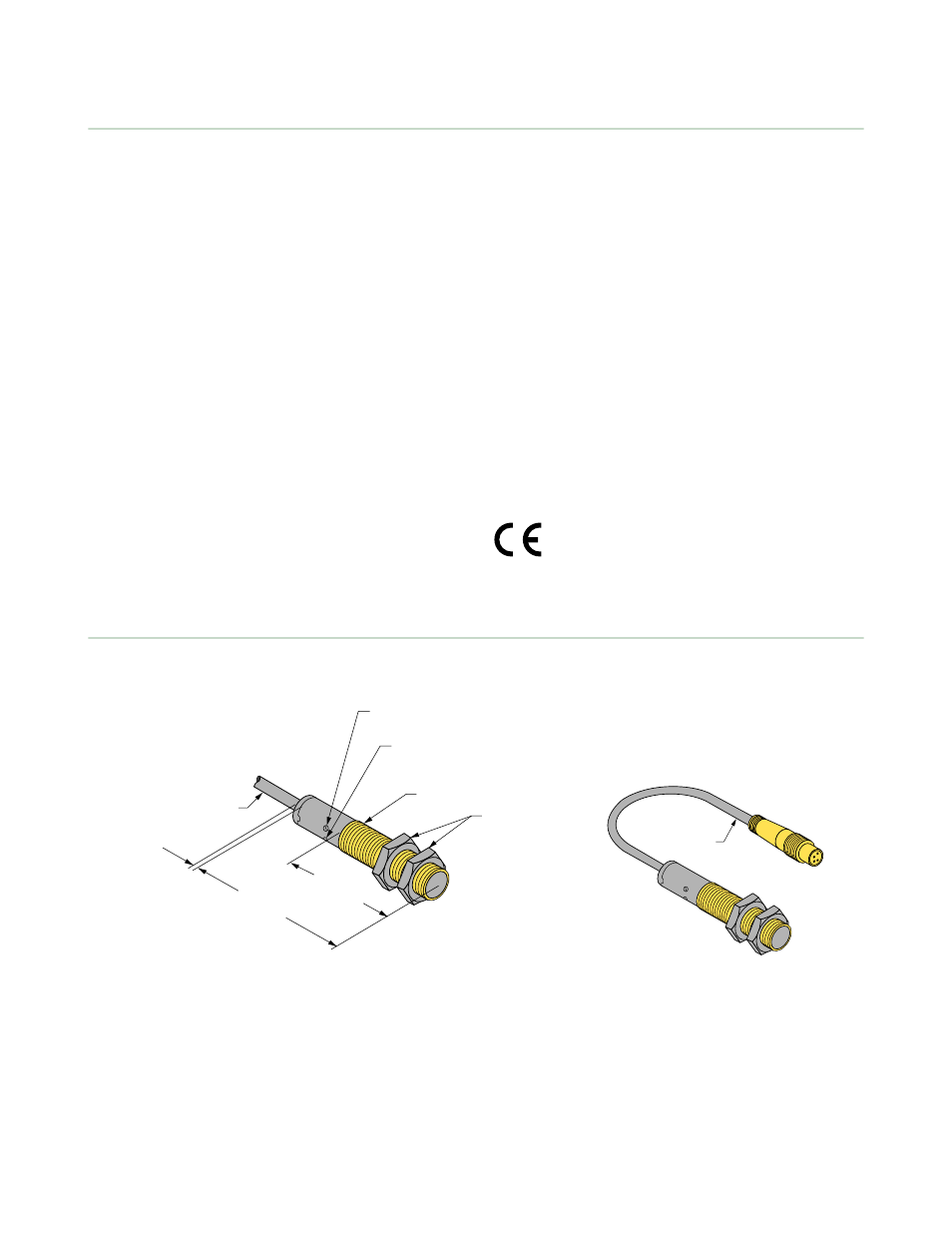
Dimensions
59.9 mm
(2.36")
4.1 mm
(0.16")
Amber LED
Output Indicator
38 mm
(1.5")
Jam Nuts
(Provided)
12 x 1 mm Thread
2 m
(6.5') Cable
Green LED
Power Indicator
Figure 1. Cabled Models
150 mm
(6") Pigtail
Figure 2. Pigtail Quick Disconnect Models
EZ-BEAM S12 Series Opposed-Mode Sensor Pairs
2
www.bannerengineering.com - tel: 763-544-3164
P/N 34501 Rev. B