D12fph series, Specifications, d12fph series sensors, Din rail fiber optic sensors – Banner D12 Series User Manual
Page 2: Sensor model listing, Application caution, 2hookup diagrams, d12fph series sensors
Specifications, D12FPH Series sensors
Sensing range:
see individual excess gain curves, page 3.
Sensing beam:
visible red, 660 nanometers.
Supply voltage:
10 to 30V dc at 45 mA max, exclusive of load.
Protected against reverse polarity and inductive load transients.
Sensor model listing
and output configurations:
Solid-state dc outputs:
D12SN6FPH NPN sinking complementary outputs, attached cable.
D12SN6FPHQ NPN sinking complementary outputs,
6-inch pigtail with pico-style
QD.
D12SP6FPH PNP sourcing complementary outputs, attached cable.
D12SP6FPHQ PNP sourcing complementary outputs,
6-inch pigtail with pico-style
QD.
The N.C. (normally closed) output may be used as an alarm output,
depending upon the hookup to the power supply.
Output rating
: 150 mA maximum each output. No false pulse on
power-up. (False pulse protection circuit causes a 20 millisecond delay
on power-up.) Short-circuit protected.
Off-state leakage current <10 microamps at 30V dc.
On-state saturation voltage <1V at 10 mA dc; <1.5V at 150 mA dc.
The total load may not exceed 150 mA.
Response time:
.5 millisecond "on"; .5 millisecond "off".
Repeatability is 130 microseconds.
Response time and repeatability are independent of signal strength.
Indicators:
Two top-mounted LED indicators, one yellow and one
green, and one 7-segment red LED moving-dot bargraph.
GREEN LED lights to indicate
DC POWER ON
.
YELLOW LED lights to indicate
NORMALLY OPEN OUTPUT CON-
DUCTING
.
7-segment moving dot red LED bargraph lights to indicate relative
received light signal strength. In addition, segment #1 flashes to
indicate
OUTPUT OVERLOAD
, and segment #7 flashes to indicate
MARGINAL EXCESS GAIN
(a "dark" signal that lights LED #2 for at
least one second, or a "light" signal that lights LED #3 for at least one
second). A flashing LED corresponds to the “on” state of the alarm
output. See page 1 for further description.
Adjustments:
SENSITIVITY control on top of module (15-turn
slotted brass screw, clutched at both ends of adjustment).
Construction:
Black ABS (Cycolac
®
KJB) housing with acrylic
cover. Rated NEMA 2. The fiber clamping element is Delrin
®
.
Cable:
6-1/2-foot long (2 meter) attached PVC-covered cable*
or 6-inch pigtail with pico-style 4-pin QD connector. Use mating
cable model PKG4-2 (straight connector) or PKW4-2 (right angled);
6-1/2 feet (2 m) long. *Models also available with 30 ft (9 m)
attached cable.
Mounting bracket:
D12 Series sensors mount directly to a stan-
dard DIN rail, or may be through-hole mounted using the supplied
mounting bracket and M3 x 0,5 stainless steel hardware. Bracket
material is black VALOX
®
.
Operating temperature range:
-20° to +70°C (-5° to +158°F).
Maximum relative humidity 90% at 50°C (non-condensing).
Application caution...
D12 Series sensors are designed to deliver very high optical energy
(excess gain). They should not be used for applications which offer
low optical contrast (i.e. only a small difference in received light levels
between the light and dark sensing conditions). Examples include
diffuse mode sensing of objects in front of a reflective background
and opposed mode sensing of non-opaque materials.
D12 sensors excel in applications requiring high excess gain (e.g.
for long-range sensing, sensing with long fiber lengths, diffuse sensing
of materials with low reflectivity, etc.)
2
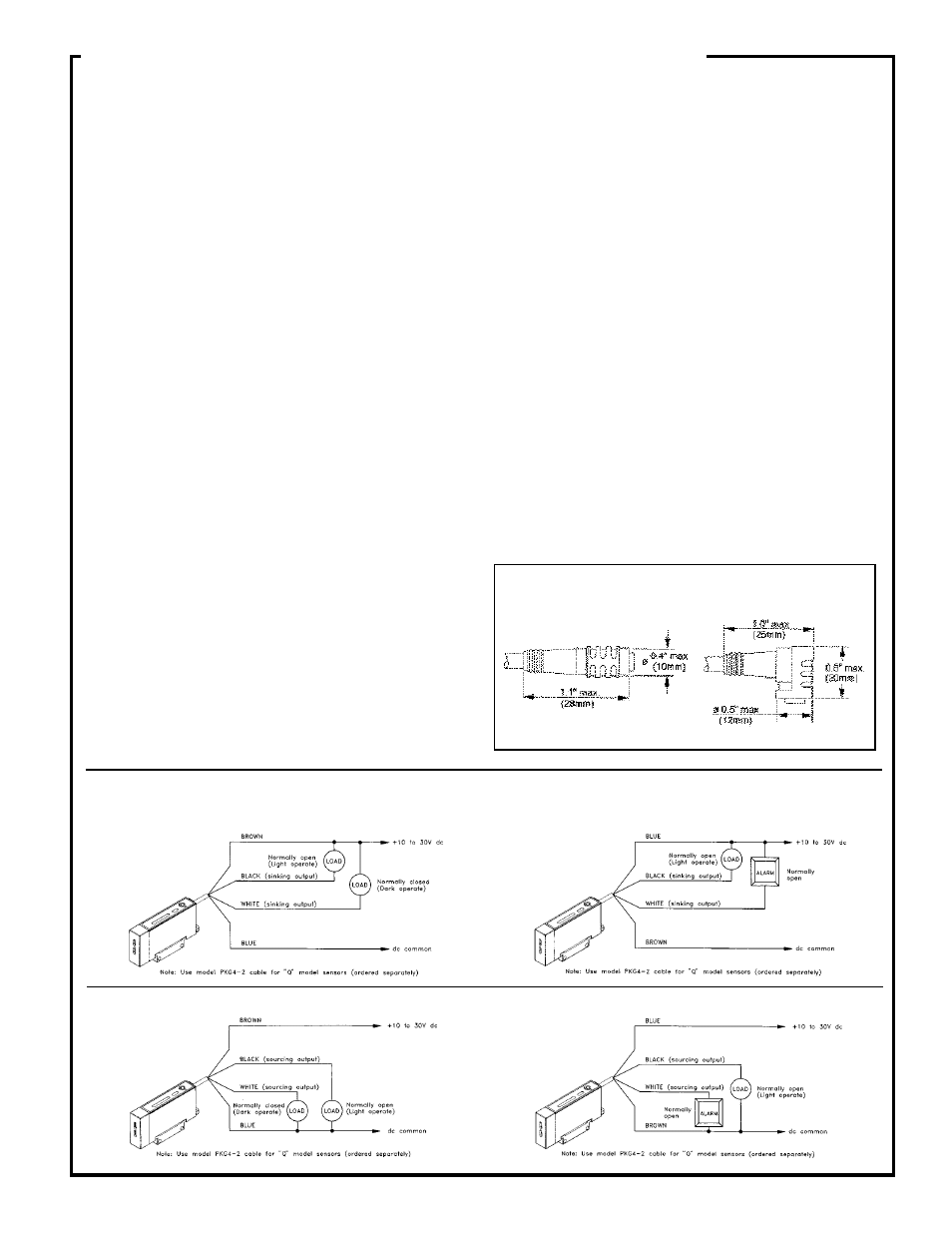
Hookup Diagrams, D12FPH Series Sensors
Sinking (NPN)
Sinking (NPN)
Standard Hookup
Alarm Hookup
Sourcing (PNP)
Sourcing (PNP)
Standard Hookup
Alarm Hookup
Model PKG4-2 cable
Model PKW4-2 cable
D12FPH Series
DIN RAIL Fiber Optic Sensors