45sd, Bus expansion cards, Quick-disconnect cable – Banner Q45 Series User Manual
Page 2: Functional schematic
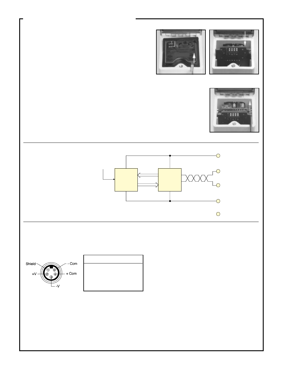
Q45X sensor hookup, 45SD expansion card installed
(Q45X base, male connector):
Removal
Modules are removed through the top of the sensor. The procedure is as follows:
1) Follow steps 1 through 3 of the Installation Procedure, above.
2) Insert a small, flat bladed screwdriver or similar tool into the lift slot on the edge of the expansion card (Photo 3).
Gently pry up to disconnect the card, and then lift it out.
Lift here
Photo 1.
Photo 2.
Lift board up and out
Photo 3.
Slide board downward
45SD
Bus Expansion Cards
Functional Schematic
Q45X Bus Configuration
(bus card installed)
Quick-disconnect Cable
Installation
Modules are installed through the top of the sensor.
The procedure is as follows:
1) Remove power from the sensor.
2) Loosen the top cover hold-down screw and raise the cover. The cover is hinged at
the front.
3) Using a small screwdriver inserted into one of the slots at the rear of the inside black
cover, lift up and remove the black inside cover (Photo 1).
4) Insert the card in the expansion slot so that the connector receptacles on the card align with the connector pins
inside the sensor. Slide the card down into the slot until the connectors are fully engaged. (Photo 2).
5) Replace the original black inside cover with the one supplied with the 45SD card.
6) Ensure that the sensor's LO/DO (light/dark operate selector) switch is in the LO position.
7) Place one of the stick-on labels (provided) over the SDS logo on the black cover.
Write the sensor's network address on the label.
Installation and Removal,
45SD Plug-in Bus Expansion Card
Pin Wire*
Function
1
Shield
2
Brown
BUS power (+V)
3
Blue
BUS power (-V)
4
Black
Communications +
5
White
Communications -
The Q45X sensor with 45SD expansion card installed requires
SDS
™
compatible quick disconnect cable, which is available from
various manufacturers including Turck, Brad Harrison, and Lumberg.
*Wire colors in the table above are for SDS
™
compatible cable only.
2
+V (pin 2)
-V (pin 3)
Shield (pin 1)
Com + (pin 4)
Com - (pin 5)
Sensing
Circuit
Bus
Card
Installed
Expansion
Slot