Q60v series adjustable-field sensors, Visible red emitter, Q60afv overview – Banner Q60 Background Suppression Series User Manual
Page 2
Q60V Series Adjustable-Field Sensors –
Visible Red Emitter
page
2
Banner Engineering Corp.
•
Minneapolis, MN U.S.A.
www.bannerengineering.com • Tel: 763.544.3164
Q60AFV Overview
The Q60AFV sensor is a full-featured adjustable-field sensor.
These adjustable-field sensors are able to detect objects of
relatively low reflectivity, while ignoring other objects in the
background (beyond the cutoff point). The cutoff distance is
mechanically adjustable, using the 2-turn adjustment screw on
the sensor top (Figure 1). A rotating pointer indicates the
relative cutoff position. (The indicator moves clockwise to show
increasing distance.)
Two push buttons (ON Delay and OFF Delay) are used to set the
output delay options, to toggle between light and dark operate
modes and to lock out the push buttons for security purposes.
These functions also may be accomplished using the remote wire.
Seven LED indicators show, during RUN mode, the sensor
configuration and operating status. During Delay Configuration,
5 of the LEDs combine to form a single light bar that indicates
relative ON or OFF delay time.
Adjustable-Field Sensing — Theory of Operation
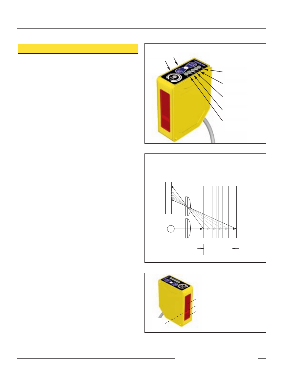
In operation, the Q60AFV compares the reflections of its
emitted light beam (E) from an object back to the sensor’s two
differently-aimed detectors R1 and R2 (see Figure 2). If the
near detector (R1) light signal is stronger than the far detector
(R2) light signal (see object A, closer than the cutoff distance),
the sensor responds to the object. If the far detector (R2) light
signal is stronger than the near detector (R1) light signal (see
object B, object beyond the cutoff distance), the sensor ignores
the object.
The cutoff distance for Q60AFV sensors is adjustable from 200
to 1000 millimeters (8" to 40"). Objects lying beyond the cutoff
distance are ignored, even if they are highly reflective. However,
it is possible to falsely detect a background object, under
certain conditions (see Background Reflectivity and Placement,
page 3).
In the drawings and discussion on this page and page 3, the
letters E, R1, and R2 identify how the sensor’s three optical
elements (Emitter “E”, Near Detector “R1”, and Far Detector
“R2”) line up across the face of the sensor. The location of
these elements defines the sensing axis (see Figure 3). The
sensing axis becomes important in certain situations, such as
those illustrated in Figures 8 and 9.
Figure 1. Q60V features
Figure 3. Q60V sensing axis
Light Sensed
Indicator
ON/OFF Delay
Push Buttons
and Indicators
Cutoff
Adjustment
Screw
Light Operate
Selected
Dark Operate
Selected
Output Conducting
(Bi-color Amber/Green)
Push Button
Lockout Indicator
Indicators Below Also
Function as a
5-Segment Light Bar During
Delay Selection Modes
R1
R2
Lenses
Object
A
Object B
or
Background
Sensing
Range
Cutoff
Distance
E
Receiver
Elements
Near
Detector
Far
Detector
Figure 2. Adjustable field sensing concept
Receiver
Elements
Emitter
When an object approaches
from the side, the most
reliable sensing usually
occurs when the line of
approach is parallel to the
sensing axis.
Sensing
Axis