Banner MICRO-AMP Series User Manual
Micro-amp, System, Ma4g 4-input gate logic module
"AND": all inputs low energizes N/O output.
Any input(s) high energizes N/C output.
"NOR": all inputs high energizes N/O output.
Any input(s) low energizes N/C output.
"X-NOR" ("exclusive NOR"):
All inputs the same energizes N/O output.
All inputs not the same energizes N/C output.
MICRO-AMP
®
System
MA4G 4-input Gate Logic Module
Printed in USA
P/N 03351F3C
MICRO-AMP
®
module MA4G is a 10 to 30V dc, plug-in, 4-input logic gate module. It
offers three selectable logic modes: "AND", "NOR", and "X-NOR" (exclusive "NOR").
In the AND gate mode, the output(s) will change state when all four inputs are low simul-
taneously. The NOR logic mode requires that all four inputs be high at the same time for
the output(s) to change state. The output(s) will change state in the X-NOR mode when
all four inputs are simultaneously either high or low. The MA4G may be used as a 2, 3
or 4-input gate. Unused inputs are simply tied low (to pin #3) or left unconnected (high),
depending upon the logic mode in use.
The MA4G directly accepts the outputs of other MICRO-AMP modules plus the NPN
(current sinking) output of self-contained dc sensors in the following Banner families:
OMNI-BEAM, MULTI-BEAM, MAXI-BEAM, VALU-BEAM, MINI-BEAM, ECONO-
BEAM, QØ8, Q19, Q25, S18, SM3Ø, C3Ø, and SM512 Series.
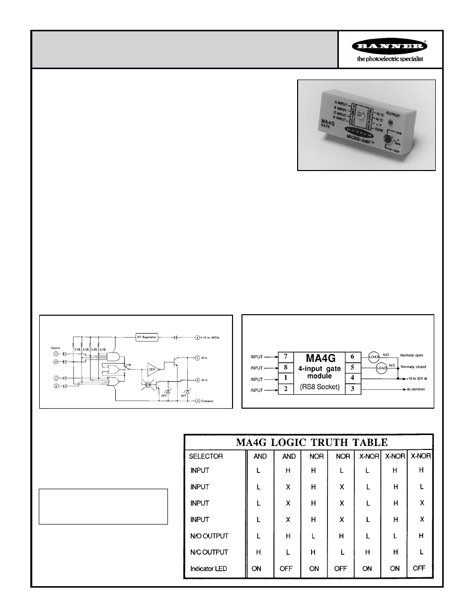
This table lists the various input states and their corre-
sponding outputs available in each logic mode. The key
to reading the table is given below. Logic statements in
the table read down the columns. For example, in the
first column, if the selector control is at "AND" and all
four inputs are logic low, the MA4G's N/O output is low,
the N/C output is high, and the LED indicator is "on".
Truth Table
H = logic HIGH
L = logic LOW
X = either HIGH or LOW (does not matter)
Truth Table Key
Hookup Diagram, MA4G LOGIC Module
voltage less than 0.5V dc at 10 milliamps. Off-state leakage current
less than 1 microamp.
SELECTOR SWITCH: single-turn potentiometer selects logic
mode. Fully clockwise = NOR mode; fully counterclockwise = AND
mode; midpoint = X-NOR mode.
INDICATOR: red LED indicator on the top of the module lights
whenever the N/O output is conducting.
CONSTRUCTION: totally encapsulated plug-in package with
molded VALOX
®
housing. Gold-flashed connection pins.
OPERATING TEMPERATURE:
0 to 70 degrees C (32 to 158 degrees F).
MICRO-AMP MA4G Specifications
SUPPLY VOLTAGE: 10 to 30V dc at less than 20 milliamps (exclu-
sive of load); 10% maximum ripple.
INPUTS: INPUT and INHIBIT both respond to a logic "low" signal
(less than 2V dc). A logic "high" is at least 6V dc or an open circuit.
Inputs must be capable of sinking at least 4 milliamps. Inputs may
be derived from limit switches or from dc sensors with NPN (current
sinking) output transistors.
RESPONSE SPEED: all INPUTS will respond to a low signal or
high signal of 1 millisecond duration or longer.
OUTPUT CONFIGURATION: two open-collector NPN transistors
with complementary outputs (one normally open, one normally closed).
Maximum sinking current 150 milliamps, each output. Saturation
Functional Schematic, MA4G LOGIC Module