2 connecting the ultrafiltration cell, Connecting the ultrafiltration cell, Figure 4 – Metrohm Inline-Ultrafiltration User Manual
Page 17
■■■■■■■■■■■■■■■■■■■■■■
3 Installation
IC equipment: Inline-Ultrafiltration
■■■■■■■■
11
3.2
Connecting the ultrafiltration cell
This chapter describes how to establish the capillary connections of the fil-
tration system (regardless of whether the filtration cell is installed on the
Sample Processor or in the ion chromatograph). It does not, however,
describe the tubing configuration for the peristaltic pump. Please refer to
the chapter "Installing the peristaltic pump" in the manual for the Sam-
ple Processor or the ion chromatograph for this information.
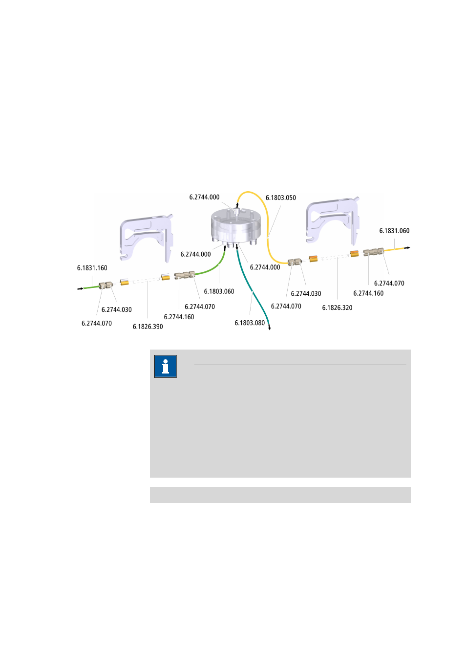
The following figure shows a schematic overview of all capillary connec-
tions of the filtration system.
Figure 4
Connecting the ultrafiltration cell
NOTE
■
In order to keep dead volume to a minimum, make sure that the
capillaries are as short as possible.
■
The capillaries that are used for transferring the filtrate are thinner
than the capillaries used for transferring the sample.
■
To prevent the capillaries leading into the ion chromatograph from
being pinched, always guide them through the capillary feed-
throughs provided for this purpose (see the manual for the ion chro-
matograph).
Connecting the ultrafiltration cell
Required accessories
■
Ultrafiltration cell (6.2729.110)
■
PTFE capillary, 0.5 mm ID / 20 cm (6.1803.050)
■
PTFE capillary, 0.97 mm ID / 20 cm (6.1803.060)
■
PTFE capillary, 0.97 mm ID / 1 m (6.1803.080)