Notice, Warning – Briggs & Stratton 10000 Watt User Manual
Page 14
14
BRIGGSandSTRATTON.COM
Final Installation Considerations
Engine Oil
notice
Any attempt to crank or start the engine before it has been
properly serviced with the recommended oil will result in
equipment failure.
Refer to Maintenance and engine manual for oil fill
information.
Damage to equipment resulting from failure to follow this
instruction will void engine and generator warranty.
•
•
This engine is shipped from the factory pre-run and filled
with synthetic oil (API SJ/CF 5W-30W). This allows for
system operation in the widest range of temperature and
climate conditions. Before starting the engine, check oil level
and ensure that engine is serviced as described in the engine
operator’s manual.
NOTE: The use of synthetic oil does not alter the required oil
change intervals described in the engine operator’s manual.
Battery
The installer must supply and install a 350 CCA (cold
cranking amps), sealed, valve-regulated, lead-acid
rechargeable 12 Volt DC, AGM type, starting battery.
NOTE: DO NOT use a deep-cycle or automotive type battery.
Install the battery as described in Servicing the Battery in the
Maintenance section of the operator’s manual. Always make
sure the negative cable is hooked up last.
The battery may not be at full charge when installed. If
battery voltage is below 12 Volts, charge the battery. See
Battery in Maintenance of the operator’s manual for details.
WARNING
Battery posts, terminals and related accessories contain
lead and lead compounds, chemicals known to the State
of California to cause cancer and reproductive harm.
Wash hands after handling.
Fuel Supply System
Ensure that all fuel pipe connections are tight, secure and
without leaks.
Ensure that all gas line shutoff valves are OPEN and that
adequate fuel pressure is available whenever automatic
operation is desired.
Fuel System Selection
The engine of your Home Generator System is factory
calibrated to run on natural gas (NG). It may also be
operated on liquefied petroleum (LP) vapor. There is no
additional hardware/equipment required to switch between
either fuel. However, LP fuel inlet pressure must be between
11 and 14 inches water column.
To configure the fuel system for LP use:
1. Remove control panel and oil fill access covers.
2. Set generator’s system switch to OFF.
3. Remove 15 Amp fuse from control panel.
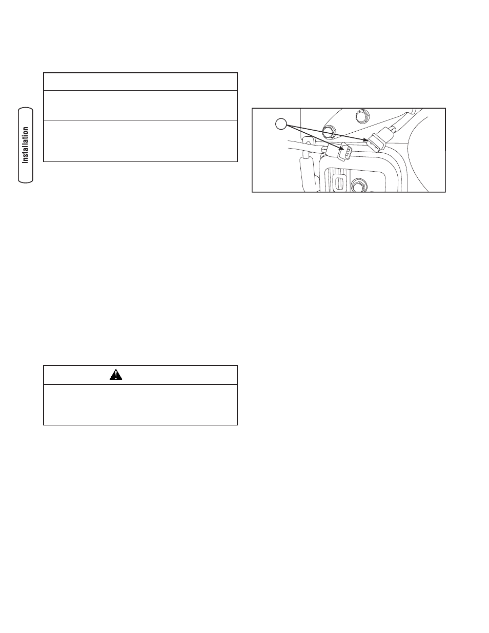
4. Connect the fuel select solenoid by joining the two-pin
electrical connector (A).
5. Reinstall 15 Amp fuse in control panel.
6. Set generator’s system switch to AUTO.
7. Install control panel and oil fill access covers.
The system is now ready to operate automatically using LP
fuel. With a fixed main jet for LP gas, there is no need to
perform any engine adjustments for LP operation.
Initial Start-up (No Load)
Before operating the home generator or placing it into
service, inspect the entire installation carefully.
Then begin testing the system without any electrical loads
connected, as follows:
1. Set generator’s main circuit breaker to its ON (closed)
position.
2. Install 15 Amp fuse in control panel.
3. Set generator’s system switch to AUTO.
4. Push MANUAL OVER-RIDE button on control panel.
NOTE: When the home generator is started for the very
first time, it will require that air in the gaseous fuel lines be
purged. This may take a few minutes.
5. DO NOT crank engine for more than 10 seconds, then
pause for 10 seconds to reduce heat in the starter.
6. Repeat process until engine starts.
7. Listen for unusual noises, vibration or other indications of
abnormal operation. Check for oil leaks while engine runs.
8. Let engine warm up for about five minutes to allow
internal temperatures to stabilize.
9. Connect an accurate AC voltmeter and a frequency
meter to check generator output at load side of circuit
breaker. Voltage should be 239-262 Volts, frequency
should be 62.0 - 62.5 Hz.
NOTE: If either parameter is outside these ranges, perform
the Engine Adjustments described below.
10. Check generator output between one of the generator
connection lugs and the neutral lug, then between the
other generator connection lug and the neutral lug.
In both cases, voltage reading should be between
119-131 Volts.
A