Briggs & Stratton 10000 Watt User Manual
Page 13
13
Generator AC Connection System
A single-phase, three-wire AC connection system is used in
the home generator. The stator assembly consists of a pair
of stationary windings with two leads brought out of each
winding. The junction of leads 22 and 33 forms the neutral
lead. Keep field wiring to a minimum. A complete schematic
and wiring diagram can be found in the separate operator’s
manual.
NOTE: Neutral is not bonded to ground at generator.
Grounding the Generator
Ground the home generator per applicable codes, standards,
and regulations. The generator GND lug is located in the
control panel box.
Utility Circuit Connection
“240V Utility” leads must be routed in conduit. The
“240V Utility” leads deliver power to the generator’s circuit
board, optional battery warmer and optional oil warmer. This
power also charges the battery. When power on these leads
is lost, the generator will start.
Using provided 2 pole connector plug and installer-supplied
minimum 300V, 14 AWG copper wire, connect each control
circuit terminal in the generator to the two-amp fuse
terminals in the automatic transfer switch.
Fault Detection System
The generator may have to run for long periods of time with
no operator present. For that reason, the system is equipped
with sensors that automatically shut down the generator in
the event of potentially damaging conditions, such as low
oil pressure, high oil temperature, over speed, and other
conditions. Refer to Fault Detection System in the Operator’s
Manual for more detailed information.
The owner will use the remote LED indicator to observe the
status of the home generator system. Consult with the owner
for a convenient location. To install the remote LED indicator:
1. Push the LED through the mounting plate from the
front until it snaps in place.
IMPORTANT: The LED is polarity sensitive.
2. Using provided 10 pole connector and installer-supplied
minimum 18AWG wire, connect the remote LED to the
generator control board +LED and GND connection.
Use wire nuts to attach wire to LED leads.
3. Attach mounting plate to installer-supplied electrical box.
NOTE: Locate the electrical box in an area visible by the
home owner such as near a garage door opener or security
control panel.
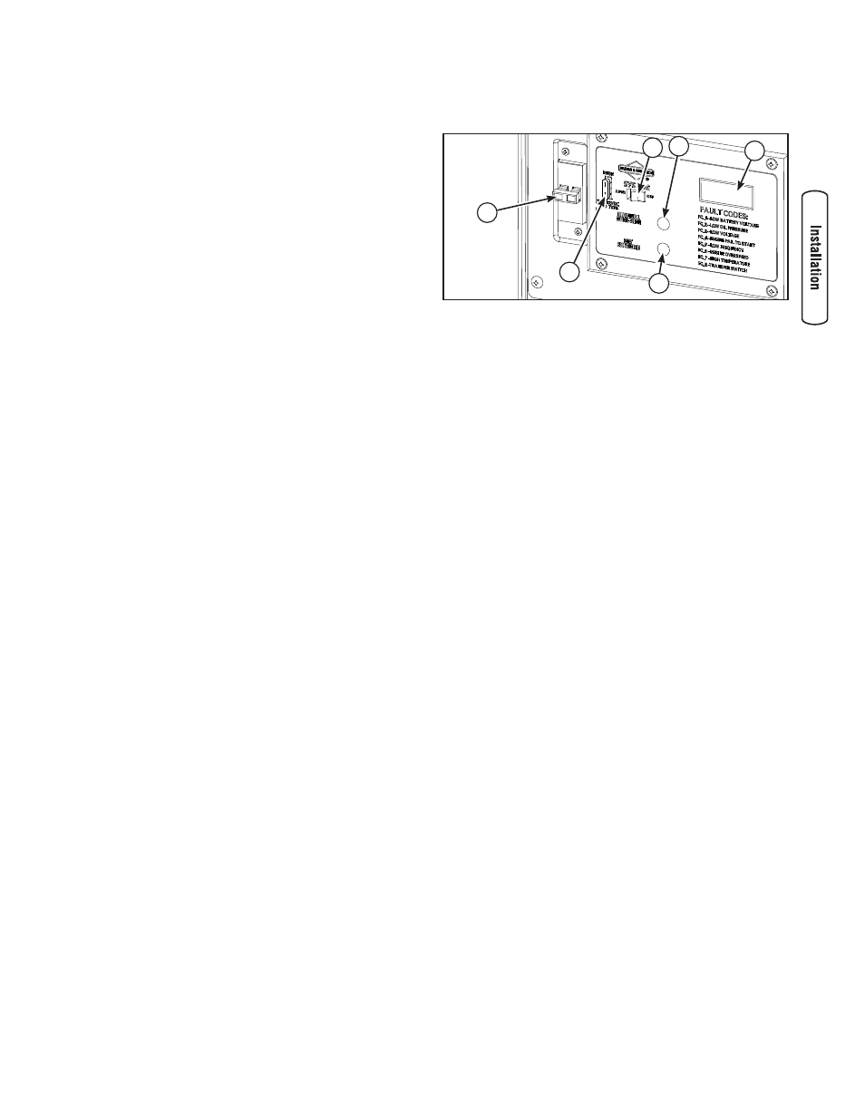
System Control Panel
The home generator control panel, located inside the
generator housing, is shown below.
Brief descriptions of the controls used during installation are:
A - System Switch — Switches modes to OFF and AUTO.
B - Manual Over-Ride Switch — Turns generator ON or OFF.
C - Digital Display — Displays running time and fault codes.
D - Set Exercise Switch — Used to set the exercise cycle.
E - 15 Amp Fuse — Protects the DC control circuits.
F - Circuit Breaker — Must be ON to supply power to the
transfer switch.
More information may be found in Controls in the Operator’s
Manual.
System Switch
This two-position switch is the most important control on
the home generator and is used as follows:
• “AUTO” position is the normal operating position. If
a utility power outage is sensed, the system will start
the generator. When utility power is restored, lets the
engine stabilize internal temperatures, shuts off the
generator, and waits for the next utility power outage.
• “OFF” position turns off running generator, prevents
unit from starting and resets any detected faults.
15 Amp Fuse
Protects the home generator DC control circuits. If the fuse
has ‘blown’ (melted open) or was removed, the engine
cannot crank or start. Replace the fuse using only an
identical ATO 15A fuse. One spare fuse is supplied with the
unit. If fuse was blown or removed, you will need to reset
the excercise timer (see Setting Excercise Timer).
F
E
A
B
C
D