Clay Paky GLOW UP STRIP 100 & FLIGHT CASE (F21250) User Manual
Page 6
6
GLOW UP STRIP 100
CONTROL PANEL
Connections to the power mains - Fig. 5
DMX 512
DMX 512
5 PIN
Power Supply
5
6
Connections to the control signal line (DMX) - Fig. 6
Use a cable conforming to specifications EIA RS-485: 2-pole twisted, shielded, 120Ω characteristic impedance, 22-24 AWG, low capacity. Do not use
microphone cable or other cable with characteristics differing from those specified. End connections must be made using XLR type 3-pin male/female
connectors. A terminating plug must be inserted on the last projector with a resistance of 120 (minimum 1/4 W) between terminals 2 and 3.
IMPORTANT: The wires must not make contact with each other or with the metal casing of the connectors. The casing must be connected to the shield
braid and pin 1 of the connectors.
2
3
1
1
2
3
4
4
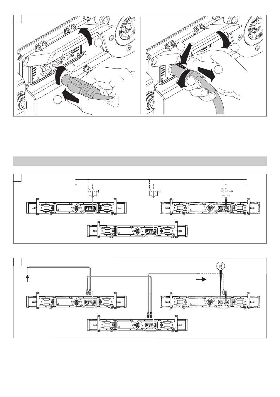
Connecting and disconnecting the power cord - Fig. 4
When connecting the power cord the user can choose whether to use the GLOW UP in one of the following ways:
1) Power cord connected for battery charge.
2) Power cord connected for projector power (thus bypassing battery operations).
The GLOW UP cannot work in both ways simultaneously.