Operating instructions, Chapter 3, Description of controls – Bird Technologies 4201 Series User Manual
Page 19
Chapter 3
Operating Instructions
A description of all operator controls and indicators are provided in this chapter.
Read and become familiar with the following instructions
before operating the
wattmeter.
Description of Controls
The controls of the wattmeter are on the front of the unit. Refer to the proper section
for your model.
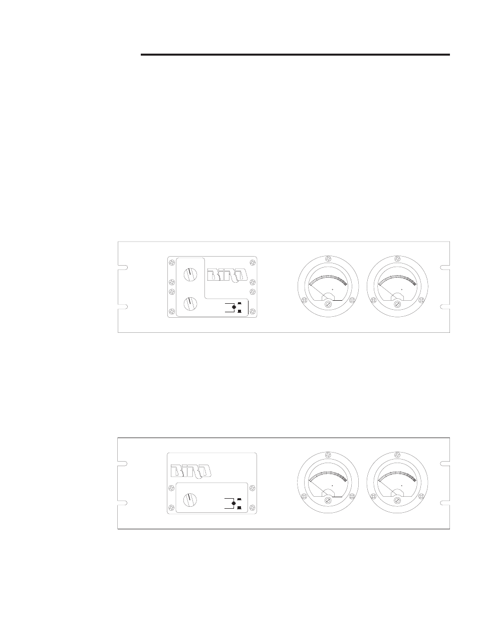
Models 4201A501
and 4201A503
These models have 24 channels for transmitters. They have two rotary channel
selector switches and a channel A/B push button. Refer to figure 6.
Models 4201A502
and 4201A504
These models have 12 channels for transmitters. They have one rotary channel
selector switch and an enable/disable push button. Refer to figure 7.
All models include two meters for simultaneous display of forward and reflected
power at
±
5% of full scale.
CHANNEL B
CHANNEL A
3
2
1
4
5
6
14
13
16
15
17
18
MODEL 4201
24 CHANNEL RF POWER METER
11
12
10
8
7
9
23
24
21
22
B
A
20
19
FWD
15
80
F.S. = 30 UA.
PN 2080 - 002
W
ELECTRONIC
20
0
BIRD
10
5
30
40
T
T
A
THRULINE
60
S
CORP.
R
20
10
40
50
100
20
RFL
20
T
40
THRULINE
ELECTRONIC
PN 2080 - 002
0
20
W
BIRD
T
A
10
5
F.S. = 30 UA.
20
50
30
CORP.
60
S
R
40
80
100
10
15
Figure 6
Front Panel of
Model
4201A501
SENSOR INPUTS
3
2
1
4
5
6
DISABLE
12 CHANNEL RF POWER METER
ENABLE
11
12
10
8
7
9
MODEL 4201
FWD
15
80
F.S. = 30 UA.
PN 2080 - 002
W
ELECTRONIC
20
0
BIRD
10
5
30
40
T
T
A
THRULINE
60
S
CORP.
R
20
10
40
50
100
20
RFL
20
T
40
THRULINE
ELECTRONIC
PN 2080 - 002
0
20
W
BIRD
T
A
10
5
F.S. = 30 UA.
20
50
30
CORP.
60
S
R
40
80
100
10
15
Figure 7
Front Panel of
Model
4201A502
9