Checking the passband, Adjusting the passband, Multiple cavity series-notch filters – Bird Technologies 20-70-26 User Manual
Page 9
range of the filter. The air-plate type has a red
mark painted on the access barrel and one-half of
the adjusting screw, when the red marks line up
the maximum amount of capacitance is achieved.
A transmitter connected to the filter will operate
best when the reflected energy is lowest. Therefore
a return loss response curve will be used to set the
passband. The passband can be checked and
adjusted following the procedure listed below.
Checking the passband
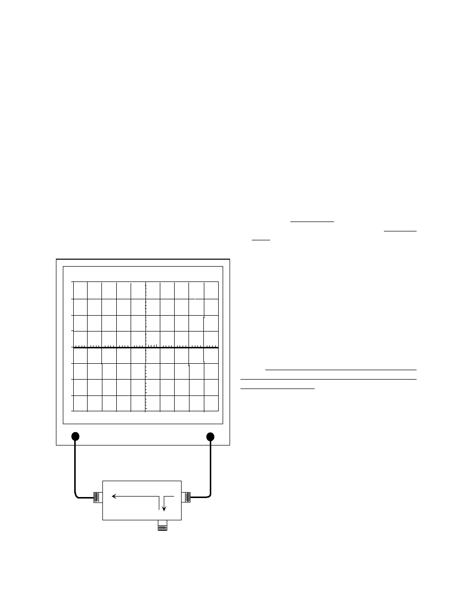
1. A zero reference for return loss must be estab-
lished at the IFR A-7550 prior to checking the
passband frequency. This is done by connect-
ing the return loss bridge to the
analyzer/generator as shown in figure 7.
2. Set-up the analyzer / generator for the desired
frequency (center of display) and for a vertical
scale of 10 dB/div.
3. Do not connect the return loss bridge to the
cavity, leave the "load" port on the bridge open.
This will supply the maximum amount of re-
flected energy to the analyzer input.
4. Insure that the IFR A-7550 menu's are set as
follows;
DISPLAY - line
MODE - live
FILTER - none
SETUP - 50 ohm/dBm/gen1.
5. The flat line across the screen is the return loss
response curve. Select the "Mode" main menu
item and then choose the "Store " command.
6. Next select the "Display" main menu item and
choose the "Reference" command. This will
cause the stored value to be displayed at the
center of the screen as the 0 dB reference
value.
7. Connect the "load" port on the RLB to the input
of the loop plate, make sure the output of the
loop plate is connected to a 50 ohm load, refer
to figure 8. The display will now present the re-
turn loss response curve for the Series-Notch
filter being measured.
Adjusting the passband
The passband is adjusted by turning the variable
capacitor in the loop plate assembly to obtain the
maximum return loss at the desired frequency or
for a maximum return loss across the frequency
band. Because of the filters sensitivity to tool
contact, an insulated tuning tool must be used to
make the adjustment.
MULTIPLE CAVITY SERIES-NOTCH FILTERS
Series-Notch filters can be ordered in multiple
cavity arrangements of either two or three
combined cavities. In these arrangements, identical
filters are connected in a cascaded fashion with the
output of each filter fed to the input port of the
succeeding filter. The advantage to this
arrangement is the amount of attenuation provided
by each of the filters is additive.
Also, the interconnecting cable between the two
filters, when cut to the correct length (odd multiple
of 1/4
λ
), will provide up to 6 dB of phase addition
due to a mismatch of impedance between the
cable and the filters. The 6 dB of mismatch
attenuation does not occur at the filters passband
TX RX Systems Inc. Manual 7-9146-1 07/25/96 Page 5
0
10
-10
-20
-30
-40
20
30
40
1
MHZ / DIV
MHZ
98.00
300
KHZ RES
dB
50
dB
ATT
GEN
dBM
0
10
MSEC
ANALYZER
GENERATE
RLB - 150 BRIDGE
LOAD
REFLECTED
SOURCE
Figure 7: Setting the return loss reference.