Converting cavity resonant filters, Table 2: conversion kit part numbers, Figure 8: checking passband frequency – Bird Technologies 20-70-26 User Manual
Page 10
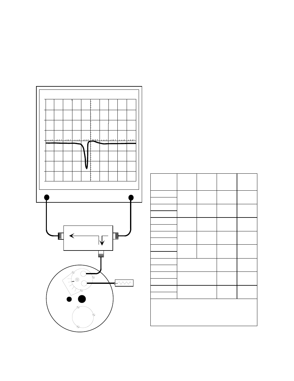
but, only at frequencies where moderate to high
attenuation occurs, such as at the notch frequency.
Because each of the filters in the multi-cavity
arrangement are identical, the passband for the
entire arrangement is generally the same as the
passband for the individual filters. However, each
filters individual insertion loss is also additive.
When tuning a multi-cavity arrangement, each filter
is tuned individually prior to interconnecting. Then
each is fine tuned to peak the overall response of
the arrangement.
CONVERTING CAVITY RESONANT FILTERS
TX RX Systems Inc. produces four types of cavity
filters, including the Vari-Notch®, Series-Notch®,
Bandpass, and T-Pass®. The cavity resonator shell
along with the coarse and fine tuning controls are
standard subassemblies found in each type of filter
for a specified frequency band. Differences
between the types are determined by the loop plate
assemblies installed in the filter.
The filter's loop plate assembly may be changed in
order to convert the cavity from one type of filter to
another. Conversion kits can be ordered which
contain all parts required for the conversion. The
available kits are listed by part number in table 2.
Refer to the appropriate TX RX Systems Inc.
manual for the specific filter type once the kit is
installed.
TX RX Systems Inc. Manual 7-9146-1 07/25/96 Page 6
Series- Notch
Filter Part #
Vari-Notch
( Lowpass )
Conversion
Kit Part #
Vari-Notch
( Highpass )
Conversion
Kit Part #
Bandpass
Conversion
Kit Part #
T-Pass
Conversion
Kit Part #
20-28-01/-11
76-28-02
76-28-03
76-28-01
76-28-07
20-28-05/-25
20-29-01/-11
76-29-02
76-29-03
76-29-01
76-29-07
20-29-05/-25
20-35-01/-11
76-35-02
76-35-03
76-35-01
76-35-07
20-35-05/-25
20-36-01/-11
76-36-03
76-36-04
76-36-01
76-38-01
20-36-05/-25
20-37-01/-11
76-37-03
76-37-04
76-37-01
76-38-01
20-37-05/-25
20-65-01/-11
76-65-03
76-65-01
76-67-01
20-65-05/-25
20-69-01/-11
76-69-03
76-69-01
76-67-01
20-69-05/-25
20-70-01/-11
76-70-03
76-70-01
76-67-01
20-70-05/-25
Note: The last two digits of the filters model number indicate it's
diameter and wavelength as listed below;
1.) Last digit of "01" indicates 6-5/8" diameter and 1/4
λ
.
2.) Last digit of "11" indicates 6-5/8" diameter and 3/4
λ
.
3.) Last digit of "05" indicates 10" diameter and 1/4
λ
.
4.) Last digit of "25" indicates 10" diameter and 3/4
λ
.
Table 2: Conversion kit part numbers.
0
10
-10
-20
-30
-40
20
30
40
1
MHZ / DIV
MHZ
98.00
300
KHZ RES
dB
50
dB
ATT
GEN
dBM
0
10
MSEC
ANALYZER
GENERATE
RLB - 150 BRIDGE
LOAD
REFLECTED
SO
URC
E
50 ohm Load
0
5
10
15
20
Series-Notch
Filter
Figure 8: Checking passband frequency.