Fine tuning rod, Assembly, Capacitor – Bird Technologies 20-70-26 User Manual
Page 6: Cavity resonator, Access barrel, Figure 5: the series-notch filter
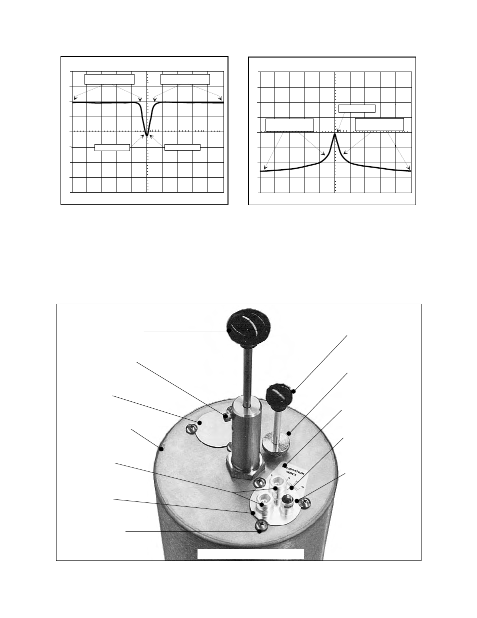
The passband is adjusted with a variable capacitor
and the notch depth is changed by rotating the loop
plate assembly. One of two input/output ports will
be marked with a red dot to indicate this particular
port has the best VSWR characteristics. The
marked port should be used as the input port. In
multiple cavity systems, the non-red dot port is
connected to the next filter's marked port.
TX RX Systems Inc. Manual 7-9146-1 07/25/96 Page 2
Cavity Resonator
Fine Tuning Rod
Fine Tuning Lock
Knurled Thumb Nut
Input/Output
Loop Plate
Hold Down Screws
Assembly
Access Barrel
Capacitor
Calibration M ar k
Calibration Index
Coarse Tuning Lock
Coarse Tuning Rod
Variable
Loop Plate
Ports
Loop Plate
Hole Cover
10-32 Cap Screw
Figure 5: The Series-Notch Filter
dB
0
10
-10
-20
-30
-40
1
MHZ/DIV
98.00
MHZ
300
KHZ/RES
10 MSEC
GEN 0 dBM
50 dB ATT
20
Passband
Low Frequency Portion
Passband
High Frequency Portion
Notch Frequency
40
30
Figure 4:
Return loss response curve for the "symmetrical"
Series-Notch filter shown in figure 3. Response curve
above is for model # 20-29-01 ( 88 - 108 MHz).
dBm
0
10
-10
-20
-30
-40
-50
-60
1
MHZ/DIV
98.00
MHZ
300
KHZ/RES
10 MSEC
GEN 0 dBM
50 dB ATT
20
Notch Frequency
Notch Depth
Passband
Low Frequency Portion
Passband
High Frequency Portion
Figure 3:
Spectrum Analyzer / Tracking Generator display of the
Series-Notch filter tuned symmetrically. Response
curve above is for model # 20-29-01 ( 88 - 108 MHz).