Adjusting the notch frequency, Cavity tuning tip, Passband – Bird Technologies 20-70-26 User Manual
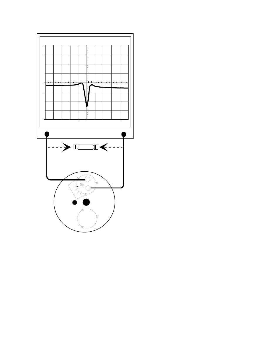
Page 8: Figure 6: checking notch depth and notch frequency
(calibrated by factory). Rotating the loop plate
assembly and moving the calibration mark above 0
causes the notch depth to be increased. It is
adjustable across a useable range of from 15 dB to
25 dB.
Adjusting the notch frequency
The notch depth should be checked and adjusted
prior to adjusting the notch frequency. The
procedure for checking the notch frequency
appears on page 3. Adjustment is made by first
setting the fine tuning knob at it's mid-point. Then
setting the peak (minimum value) of the response
curve to the desired frequency (should be the
center-vertical graticule line on the IFR A-7550's
display). See figure 6.
The resonant frequency is adjusted by using the
coarse tuning rod, which is a sliding adjustment
(invar rod) that rapidly tunes the response curve
across the frequency range of the filter. Resonant
frequency is increased by pulling the rod out of the
cavity and is decreased by pushing the rod into the
cavity. Additionally, the fine tuning rod, also a
sliding adjustment (silver-plated-brass rod), allows
a more precise setting of the frequency after the
coarse adjustment is made. The frequency is
increased by pushing the fine tuning rod in and is
decreased by pulling it out, the exact opposite of
the coarse tuning rod.
Once the desired response is obtained using the
coarse and fine tuning rods, they are "locked" in
place. The coarse rod is secured by tightening the
10-32 cap screw (5/32 hex wrench required) and
the fine tuning rod is held in place by tightening the
knurled thumb nut. Failure to lock the tuning
rods will cause a loss of temperature
compensation and detuning of the cavity.
Cavity Tuning Tip
When tuning a cavity that has been in service for
some time it is not unusual to find the main tuning
rod hard to move in or out. This occurs because
TX RX Systems Inc. uses construction techniques
borrowed from microwave technology that provide
large area contact surfaces on our tuning probes.
These silver plated surfaces actually form a
pressure weld that maintains excellent conductivity.
The pressure weld develops over time and must be
broken in order for the main tuning rod to move.
This is easily accomplished by gently tapping the
tuning rod with a plastic screwdriver handle or
small hammer so it moves into the cavity. The
pressure weld will be broken with no damage to the
cavity.
PASSBAND
The passband is the frequency range over
which the return loss is 15 dB or greater.
Because the passband will vary with the tuning of
the notch frequency it should be the last
adjustment made to the Series-Notch filter. The
passband is adjusted by changing the amount of
capacitance in the loop plate assembly. The
capacitor is variable and is either an air-plate or a
tubular-piston type depending upon the frequency
TX RX Systems Inc. Manual 7-9146-1 07/25/96 Page 4
0
1
MHZ / DIV
MHZ
98.00
300
KHZ RES
50
dB
ATT
GEN
dBM
0
10
MSEC
ANALYZER
GENERATE
10
20
30
40
dB
-10
-20
-30
-40
FEMALE UNION
Used to set 0 dB reference
0
5
10
15
20
Series-Notch
Filter
Figure 6: Checking notch depth and notch frequency.