Table 2: conversion kit part numbers – Bird Technologies 11-70 Series User Manual
Page 8
cause the stored value to be displayed on the
screen as the 0 dB reference value.
4. Connect the generator output and analyzer in-
put to the input/output ports of the loop plates
and the insertion loss will be displayed on the
IFR A-7550's screen, refer to figure 3.
5. Insertion loss is usually factory adjusted, at
which time index labels are attached to the top
of the cavity next to the loop plates and calibra-
tion marks are stamped into the loop plates
themselves. The index label serves as a relative
index with insertion loss settings keyed to index
numbers on the label. The calibration mark is
normally factory aligned so that the index value
of 10 will be equal to an insertion loss of 1.0 dB.
The relative index labels are used to log specific
filter performance. Insertion loss can be ad-
justed by loosening the 10-32 hold down screws
and rotating the loop plates.
6. Rotating the loop plate assemblies and moving
the calibration marks above or below 10 causes
the insertion loss to be increased or decreased
(above 10 increases the loss while below 10
decreases it). The insertion loss is adjustable
across a useable range of from 0.5 dB to 3.0
dB. It is important to set both loops to the
same index number so that the cavity's inser-
tion loss remains balanced.
7. The insertion loss setting determines the selec-
tivity of the filter and a change of loss will cause
a shift in the width of the passband. The pass
frequency of the cavity must be retuned after
the insertion loss is adjusted, as changes in
coupling also change the cavity's resonant fre-
quency. Repeat steps 4 and 5 of the cavity tun-
ing procedure in order to complete the cavity's
tuning.
CONVERTING CAVITY RESONANT FILTERS
TX RX Systems Inc. produces four types of cavity
filters, including the Vari-Notch®, Series-Notch®,
Bandpass, and T-Pass®. The cavity resonator shell
along with the coarse and fine tuning controls are
standard subassemblies found in each type of filter
for a specified frequency band. Differences
between the types are determined by the loop plate
assemblies installed in the filter.
TX RX Systems Inc. Manual 7-9145-1 08/05/96 Page 4
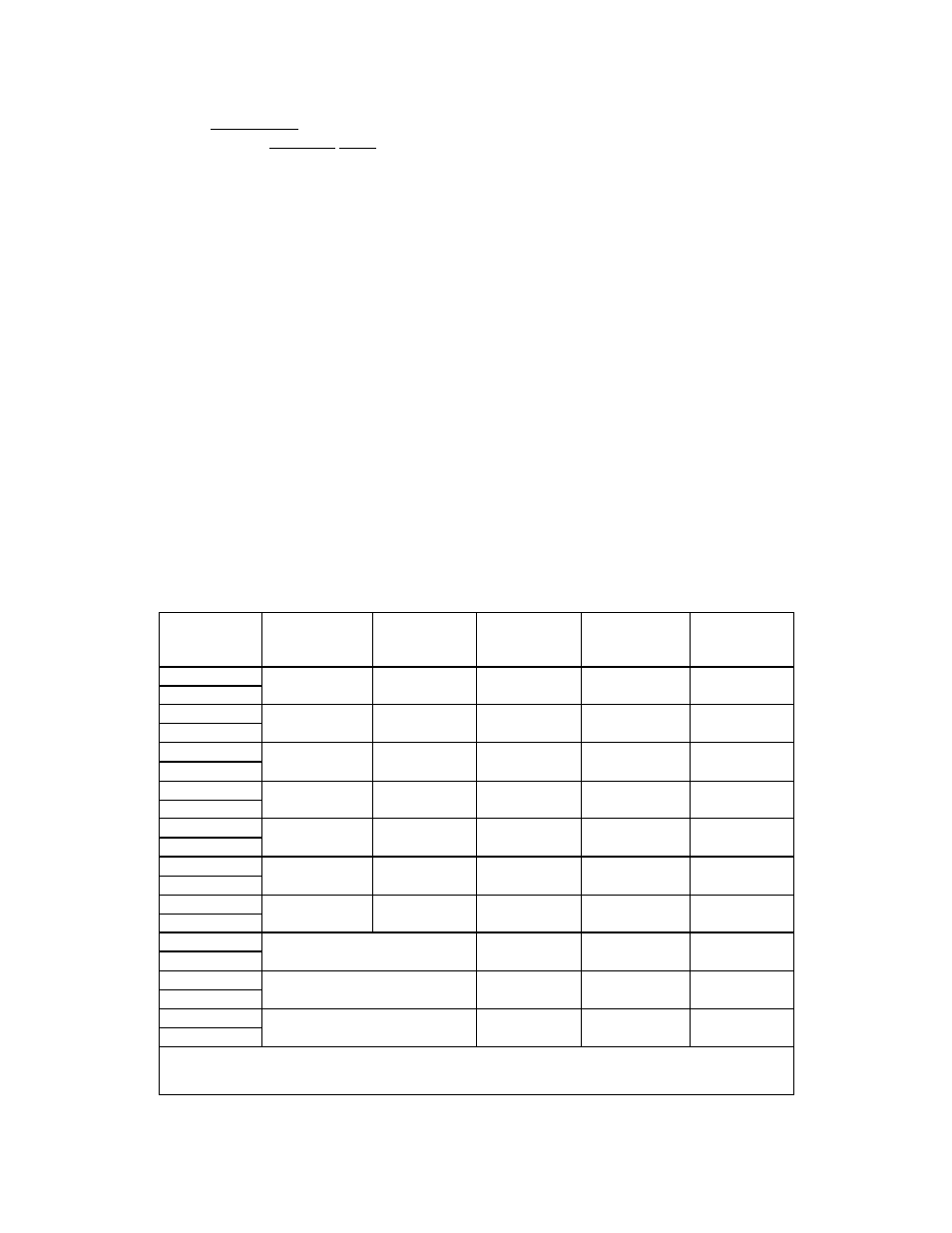
Bandpass
Filter Part #
Vari-Notch
Lowpass Conversion
Kit Part #
Vari-Notch
Highpass
Conversion
Kit Part #
Series-Notch
Lowpass
Conversion
Kit Part #
Series-Notch
Highpass
Conversion
Kit Part #
T-Pass
Conversion
Kit Part #
11-28-01
76-28-02
76-28-03
76-28-04
76-28-05
76-28-07
11-28-05
11-29-01
76-29-02
76-29-03
76-29-04
76-29-05
76-29-07
11-29-05
11-35-01
76-35-02
76-35-03
76-35-04
76-35-05
76-35-07
11-35-05
11-36-01
76-36-03
76-36-04
76-36-05
76-36-06
76-38-01
11-36-05
11-37-01
76-37-03
76-37-04
76-37-05
76-37-06
76-38-01
11-37-05
11-54-01
N/A
N/A
N/A
N/A
76-53-01
11-54-05
11-55-01
N/A
N/A
N/A
N/A
76-53-01
11-55-05
11-65-01/-11
76-65-03
76-65-04
76-65-05
76-67-01
11-65-05/-25
11-69-01/-11
76-69-03
76-69-04
76-69-05
76-67-01
11-69-05/-25
11-70-01/-11
76-70-03
76-70-04
7670-05
76-67-01
11-70-05/-25
Note: The last two digits of the filters model number indicate it's diameter and wavelength as listed below;
1.) Last digit of "01" indicates 6-5/8" diameter and 1/4
λ
. 2.) Last digit of "11" indicates 6-5/8" diameter and 3/4
λ
.
3.) Last digit of "05" indicates 10" diameter and 1/4
λ
. 4.) Last digit of "25" indicates 10" diameter and 3/4
λ
.
Table 2: Conversion kit part numbers.