Figure 3: checking cavity tuning – Bird Technologies 11-70 Series User Manual
Page 7
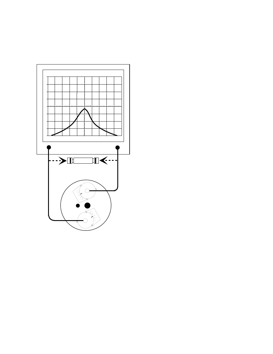
2. The resonant frequency of the filter is checked
by connecting the tracking generator to the in-
put of the cavity filter while the spectrum ana-
lyzer is connected to the output, as shown in
figure 3.
3. Insure the IFR A-7550 menu's are set as fol-
lows:
DISPLAY - line
MODE - live
FILTER - none
SETUP - 50 ohm/dBm/gen1.
4. Set the fine tuning knob at it's mid-point. Adjust
the pass frequency by setting the peak (mini-
mum loss value) of the response curve to the
desired frequency (should be the center-vertical
graticule line on the IFR A-7550's display). See
figure 3. The resonant frequency is adjusted by
using the coarse tuning rod, which is a sliding
adjustment (invar rod) that rapidly tunes the fil-
ter's response curve. The resonant frequency is
increased by pulling the rod out of the cavity
and is decreased by pushing the rod into the
cavity. Additionally, the fine tuning rod, also a
sliding adjustment (silver-plated-brass rod ), al-
lows a more precise setting of the response
curve after the coarse adjustment is made. The
resonant frequency is increased by pushing the
fine tuning rod in and is decreased by pulling it
out, the exact opposite of the coarse tuning rod.
5. Once the desired response is obtained using
the coarse and fine tuning rods, they are
"locked" in place. The coarse rod is secured by
tightening the 10-32 cap screw and the fine
tuning rod is held in place by tightening the
knurled thumb nut. Failure to lock the tuning
rods will cause a loss of temperature compen-
sation and detuning of the cavity.
Cavity Tuning Tip
When tuning a cavity that has been in service for
some time it is not unusual to find the main tuning
rod hard to move in or out. This occurs because
TX RX Systems Inc. uses construction techniques
borrowed from microwave technology that provide
large area contact surfaces on our tuning probes.
These silver plated surfaces actually form a
pressure weld that maintains excellent conductivity.
The pressure weld develops over time and must be
broken in order for the main tuning rod to move.
This is easily accomplished by gently tapping the
tuning rod with a plastic screwdriver handle or
small hammer so it moves into the cavity. The
pressure weld will be broken with no damage to the
cavity.
Measuring and Adjusting Insertion Loss
1. A zero reference must first be established at the
IFR A-7550 before the insertion loss can be
measured. This is accomplished by temporarily
placing a "female union" between the generator
output and analyzer input, see figure 3.
2. The flat line across the screen is the generator's
output with no attenuation, this value will be-
come our reference by selecting the "Mode"
main menu item and choosing the "Store"
command.
3. Next select the "Display" main menu item and
choose the "Reference" command. This will
TX RX Systems Inc. Manual 7-9145-1 08/05/96 Page 3
0
2
-2
-4
-6
-8
4
6
8
50
KHZ / DIV
MHZ
98.00
300
KHZ RES
dB
40
dB
ATT
GEN
dBM
0
10
MSEC
ANALYZER
GENERATE
FEMALE UNION
Used to determine 0 dB reference.
0
5
10
15
20
BANDPASS
FILTER
0
5
10
15
20
Figure 3: Checking cavity tuning.