Bird Technologies 11-70 Series User Manual
Page 6
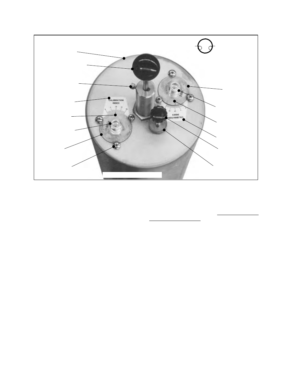
labeled in figure 1. All of the physical components
of the filter are labeled in figure 2, with the
adjustable parts shown in emboldened italics.
Coarse and fine tuning rods are used to adjust the
pass (resonant) frequency. The insertion loss is
changed by rotating the two loop plate assemblies.
TUNING
Required Equipment
The following equipment or its equivalent is
recommended in order to properly perform the
tuning adjustments for the Bandpass filter.
1. IFR A-7550 Spectrum Analyzer with optional
Tracking Generator installed.
2. Double shielded coaxial cable test leads
(RG142 B/U or RG223/U).
3. 5/32" hex wrench.
4. Connector - female union (UG29-N or
UG914-BNC)
5. Connector - tee (UG-107 B/U).
General Tuning Procedure
Tuning of the filter requires adjustment of the
pass
frequency.
The pass frequency is adjusted by
monitoring the output of a tracking generator after
it passes through the filter. Adjustment of the
insertion loss is optional on units that are preset by
the factory, which is most often the case. To insure
proper tuning of the Bandpass filter, all
adjustments should be performed in the following
order;
1. Preset loops to an index value of 10 if not fac-
tory set.
2. Tune the pass frequency.
3. Set the insertion loss if other than 1.0 dB loss is
desired.
4. Fine tune the pass frequency
Cavity Tuning Procedure
1. Setup the analyzer / generator for the desired
frequency and bandwidth (center of display) and
also a vertical scale of 2 dB/div.
TX RX Systems Inc. Manual 7-9145-1 08/05/96 Page 2
Cavity Resonator
Coarse Tuning Rod
Coarse Tuning Lock
Input/Output Port
Input/Output Port
Fine Tuning Rod
Fine Tuning Lock
Knurled Thumb Nut
Calibration Index
Calibration Index
Calibration Mark
Calibration Mark
Loop Plate
Assembly
Loop Plate
Assembly
Loop Plate
Hold Down Screws
10-32 Cap Screw
Schematic
Symbol
Figure 2: The Bandpass filter.