Bird Technologies 11-70 Series User Manual
Page 5
GENERAL DESCRIPTION
The Bandpass cavity filter passes one narrow band
of frequencies (
passband
) and attenuates all
others with increasing attenuation above and below
the pass frequency. Bandpass filters have
adjustable selectivity characteristics which allows a
trade off between insertion loss and selectivity, with
a higher loss giving greater selectivity. Maximum
power handling is determined by the insertion loss
setting. A variety of models are available that cover
the range of frequencies from 30 to 960 MHz. The
portion of the frequency range that each model will
tune across is determined by the cavity's physical
length.
Either 6-5/8" or 10" diameter resonator shells may
be used to construct the filters. The difference
between the two sizes determines the filters
selectivity and it's maximum power dissipation. The
10" diameter filters have slightly higher selectivity
compared to the 6-5/8" models and can safely
dissipate up to 40 Watts of RF Power. The 6-5/8"
filters can dissipate up to 30 Watts. Maximum input
power for the 6" and 10" diameter filters is listed in
table 1. When a filter is operated above 1.0 dB loss
in transmitter applications, we recommend
inserting a ferrite isolator between a transmitter
and the Bandpass filter because the VSWR may
exceed 1.5 : 1.
There are two adjustable parameters found in a
bandpass filter including the pass frequency and
the insertion loss. Each of these parameters is
TX RX Systems Inc. Manual 7-9145-1 08/05/96 Page 1
dBm
0
10
-10
-20
-30
-40
-50
-60
-70
98.00
MHZ
300
KHZ/RES
10 MSEC
GEN 0 dBM
40 dB ATT
1
MHZ/DIV
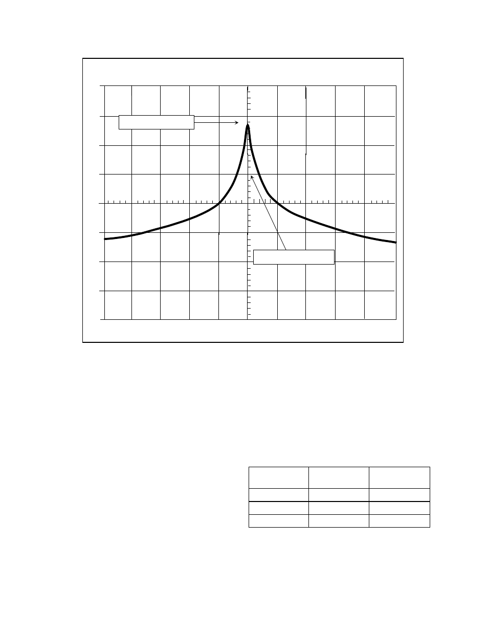
INSERTION LOSS
PASS FREQUENCY
Figure 1: Spectrum Analyzer / Tracking Generator display of the Bandpass filter.
Response curve shown for model # 11-29-01 (88 - 108 MHz)
Insertion loss
6" diameter
Power Rating
10" diameter
Power Rating
0.5 dB
275 Watts
368 Watts
1.0 dB
146 Watts
194 Watts
3.0 dB
60 Watts
80 Watts
Table 1: Input power ratings.